DMX Decoder: a Software for OpenDecoder (V.2 and V.3)
Overview
- Slowly the day the ends, the sky gets coloured red during dusk and
with the beginning of the night the sky is shining in a dark blue.
In in the model course gradually all street lamps, houses a.s.o. are turned on.
For this optical illusion the control of the room light from the model computer is needed.
The illusion also requires a large number of
lit houses,
road courses, platforms and cars.
The control of the room light can be acheived very inexpensive with DMX and commercially available DMX dimmers. A quadruple dimmer for 230V and 2kW costs about 80-100 Euro.
If OpenDecoder2 or OpenDecoder3 is loaded with the following software, then 24 DMX channels are available. The sensitive brightness control is completely taken over by the decoder. The command station sees a normal accessory decoder, which is addressed completely simply via switch switching commands.
A complete transition daylight, dusk, night and vice versa can be performed simply by one turnout command. This command may be sent by the command station or by pressing one of two locally connected tracers (for day/night). Thus this light control decoder can operate both manually and with each commercial DCC command station and all control programs.
This software implements a full accessory decoder, the programming of the dmx channels is done by means of CV (=Configuration variable). These are adjustable either by service mode or by PoM (=Programmierung on the main). The control during normal operation is then simply done with the usual switch keys. Additionally the decoder can be adjusted in its address also completely simply through pressing the programming tracer followed by an unique sending of the correct address (learn mode).
Additionally a watchdog decoder is integrated in the DMX decoder. This can supervise both the function of the command station and pc control, and in case of an emergency stop the light immediately will dimm up to full brightness.
Theory: what is DMX?
- DMX (=Digital multiplex) is a digital protocol, mainly used on stages for the control of headlights and accessories.
It uses a symmetrical signal (RS485) with 250 kbit/s. The used plugs are three pole or five-pin XLR, whereby the three pole version is not official but often used, especially in the lowcost area. The used line impedance is 120 ohms, so that shielded audio cables can be used.
| Pin allocation on DMX | ||
|---|---|---|
| Pin | 5-pin | 3-pin |
| 1 | Mass (shield) | Mass (shield) |
| 2 | Signal inverted (DMX-) | Signal inverted (DMX-) |
| 3 | Signal (DMX+) | Signal (DMX+) |
| 4 | not used/second connection (DMX-) | |
| 5 | not used/second connection (DMX+) |
The signal is routed daisy chain, the chain may contain up to 32 members and at the end there must be termination with 120 ohms. This is plugged in the last receiver. That means, a cord from the decoder is drawn to the first receiver. From the exit of this receiver the signal ist routed to the next unit, etc. All DMX receivers are thus arranged in one chain.
The selection of the respective address of the receivers takes place with DIP switches, whereby (depending upon unit) often several addresses are occupied in sequence.
Practice: Generation of the DMX signal
- Generation of the signals
The required 250kBit signal can be produced either with the serial interface or with a software loop. OpenDecoder2/3 uses the serial interface. - Programming
The decoder converts turnout commands to the control of a DMX channel with a certain brightness. The duration of the ramp until this brightness is reached is adjustable (- > virtual accessory output).
Beyond that a number of such virtual accessory output can be combined into groups and can be activated only one turnout command. (e.g. turnout command �make dusk�). This is called a -> macro.
The configuration of these virtual accessory output (ramps and target brightness) is made by CV's. Macrao again are defined with CVs. - Smooth brightness transitions
The approximation on the target brightness value takes place in very fine steps. These are calculated every 20ms with an arithmetic unit. The actual brightness is changed every 20ms to this calculated value. The complete set of brightness values are the to the DMX receivers (i.e. 50Hz update rate). This approximation takes place until the target brightness value is reached. By this technique a very gentle, almost step-free brightness control is acheived.
Application:
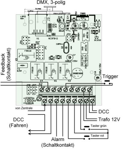
- Step 1: Wiring of the system
- At the input side the decoder at the clamps X1-1 and X1-2 is connected to the digital signal (DCC).
- A plug power pack is connected to the clamps X2-1 and X2-2 for current supply. Please use a separate all-insulated power pack, in order to ensure electrical security.
- The DMX socket is connected to the clamps X6-1,2,3; plug in a commercial XLR stage cable.
- The other end of the XLR cable is plugged into the entrance of the dimmer pack.
- At the exit of the dimmer pack a termination must be plugged in.
- At the outlet sockets of the dimmer pack the following lamps are attached:
Outlet 1 white lamp (daylight) Outlet 2 white lamp (daylight) Outlet 3 red lamp (dusk) Outlet 4 blue lamp (night)
- Step 2: Adjustments
- After power-up the red control led will flash as follows: 'X-X-X-X-X----X-X-X-X-X----' (=error code 5). This indicate that no address has been programmed so far.
- At the decoder press the "program" tracer - the red LED is permanently lit.
- Issue a turnout command a the command station; please send the first instruction from a group of four, this is either turnout 1 or 5 or 9 etc. The LED will turn off, showing that the decoder has learned this address and can be used with the commands described below.
- Step 3: Nothing more - DONE!
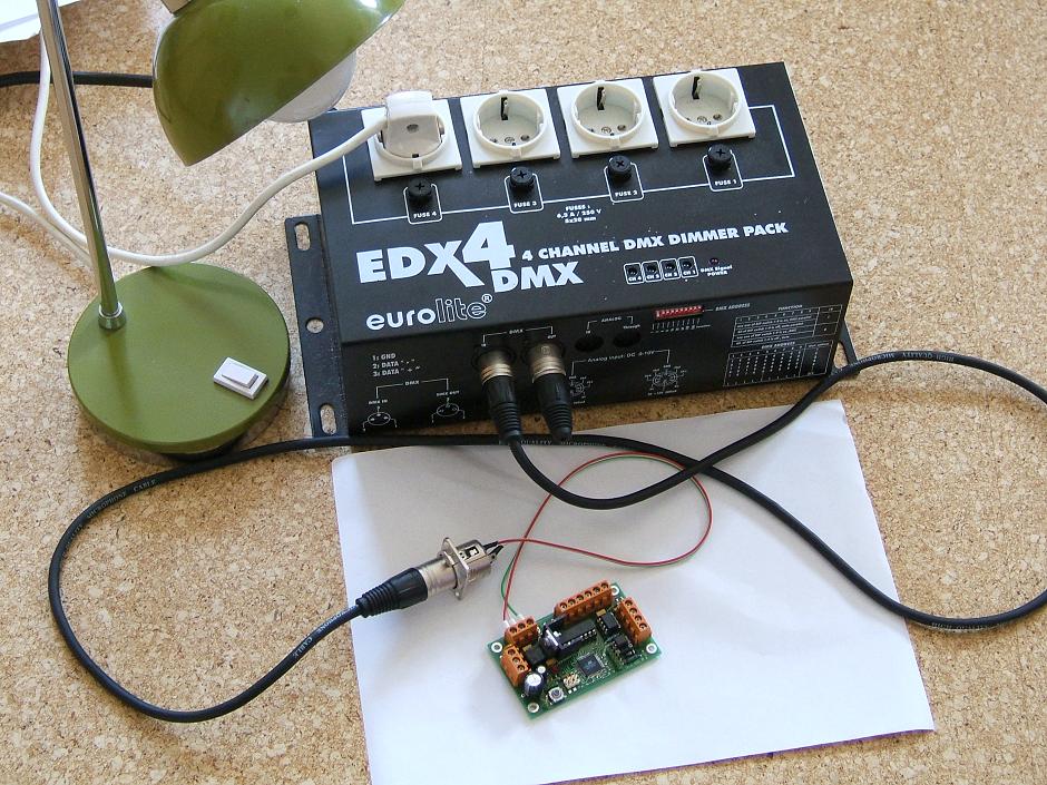
What is needed, in order to use the light control? The following quick guide describes the necessary setup using opendecoder2 with the pre-setting and a commercial dimmer (e.g. Eurolite EDX4) with 4 exits. Special programming knowledge or CV-handling is not needed.
Configuration with CV-variables
- In the initial configuration a meaningful setup for dusk and dawn is provided,
there is normally no further CV's setting required.
But if this setting is to be changed and more light shows are required, this can
be done as described below.
Some predefined sceneries are supplied in the program memory of the decoder. These may be used as
as starting point and assistance for individual configurations.
They can be loaded with the help of CV559 into the configuration memory of the decoder.
- After a write access to CV520 the following will happen: fast flashing for a short time (the decoder is copying the reset values from Flash to EEPROM), succeeded by error code 5 (since there is now no valid address in EEPROM).
- OpenDecoder2 has some memory limitations and does not preset virtual decoders. These can be clear with an access to CV559.
- Specify the general behavior
- CV 545 (33): DECODER MODE
This CV specifies the mode of operation of the decoder. Depending on the mode of the decoder the meaning of the following CV's can change completely! Pay attention - the loaded software must support the selected decoder mode.CV 545: DECODER MODE 0 turnout and signal with feedback 1 Servo decoder 2 Multipostion servo decoder 3 Relay decoder (only OpenDecoder3) 8 DMX decoder (described here) 16 Decoder for roundabout 32 Signal decoder with dimming
In the following only the CV's for the MODE 8 are described! - CV 551: DMX configuration (*=0)
Bit field for the dmx setupCV 551: DMX CONFIGURATION 7 Single call:
*0 no additional single call of DMX channels is possible, the decoder can only be addressed only via the four turnout addresses indicated below. 1 each virtual DMX decoder can be called individually. The decoder allocates 72 addresses additionally to the first 8 turnout addresses. (total: 88 addresses)
These further addresses are assigned to the respective virtual DMX decoders. Thus each programmed DMX transition can be called individually.
In this case the decoder occupies 8+72 = 80 switch addresses. The first 8 addresses are assigned to macros, the following 72 addresses are assigned to virtual decoders.6 Start position:
0 After switching on all DMX channels are off. *1 After switching on all DMX channels are put out with maximum level. 5 Reaction of lights on watchdog:
0 Watchdog does not have influence on the light. *1 when the watchdog gets triggered, the light is set to full brightness. (see also CV554-557) 4 Relay control with watchdog:
0 Watchdog will not switch relays. Relays could be switched from DMX channels 24-27 *1 when watchdog gets triggered, the assigned relays are switched. No access from DMX. 0..3 reserved - CV 552: Watchdog trigger delay (*=20)
This setting defines the time interval until the watchdog is triggered. A turnout command must be received, before this time is exceed, otherwise teh watchdog will trigger. Unit: 100ms; Range of values: 1 ... 127 (=0,1s ... 12,7s)
default: 2 seconds. - CV 553: Alarm time (*=50)
This setting defines the duration of the active alarm output (how long the alarm relay is activated). Unit: 100ms, range of values: 1 ... 127 (=0,1 ... 12,7s)
default: 5 seconds. - CV 554: Power On default for DMX channels 7 to 0 (*=255)
This bit field indicates the data content of the corresponding DMX channel after a 'all_on' event (either at power on or with a dcc command). Bit 7 maps to channel 7, bit 0 maps to channel 0. - CV 555: Power On default for DMX channels 15 to 8 (*=255)
This bit field indicates the data content of the corresponding DMX channel after a 'all_on' event (either at power on or with a dcc command). Bit 7 maps to channel 15, bit 0 maps to channel 8. - CV 556: Power On default for DMX channels 23 to 16 (*=255)
This bit field indicates the data content of the corresponding DMX channel after a 'all_on' event (either at power on or with a dcc command). Bit 7 maps to channel 23, bit 0 maps to channel 16. - CV 557: Power On default for DMX channels 31 to 24 (*=0)
This bit field indicates the data content of the corresponding DMX channel after a 'all_on' event (either at power on or with a dcc command). Bit 7 maps to channel 31, bit 0 maps to channel 24.
CV calculator:
- CV 545 (33): DECODER MODE
Going back to decoder defaults can be achieved by a write access to CV520 (=CV8).
- Notes:
Hint: easiest way to find the settings is to paint down the desired brightness-over-time plot and read out the programming values.
The decoder is able to control 24 DMX channels, these can be set up with 72 different brightness values. Such a pair (DMX channel and value) corresponds to a virtual accessory decoder. Sequences (=macros) of up to 18 such virtual decoders can be created and assigned to a turnout instruction. Note: These limitations are arbitrarily selected and can be changed in the source code.
For easier programming of the CVs a config file for TrainProgrammer was created.
In the following the configuration of the DMX decoder is described, whereby the configuration is divided into three sections:
In in the following chapters the individual configuration is described. To make this configruation easier some predefined scenarios are supplied with the decoder. These are stored in program memory and can be copied by means of a write access to CV559 into the configuration memory. The presets can be used as starting point for a individual configuration.
The write access on CV559 is acknowledged immediately, then the copy process starts. The decoder flashes during this process. It will fail if the decoder is powered down. Therefore it is urgently recommended to feed the decoder with a separate power supply. (On the programming track often the power is turned off after writing)
The selected preset changes only the virtual decoders and macros, other CVs such as address and mode are not affected.
| CV 559: DMX Preset Scenery (only for OpenDecoder3) | |||||||||||||||||||||||||
|---|---|---|---|---|---|---|---|---|---|---|---|---|---|---|---|---|---|---|---|---|---|---|---|---|---|
| Value | Scenery | ||||||||||||||||||||||||
| 0 | Scenery: cleared Virtual Decoder:
| ||||||||||||||||||||||||
| 1 | Scenery: Direct control, light demonstration, RGB circle Virtual Decoder:
| ||||||||||||||||||||||||
Each output and the desired target brightness must be assigned to a virtual accessory decoder. For every such virtual decoder, the setup of four CV's is required:
- The DMX channel, which is assigned to this virtual decoder.
when called, this DMX channel is changed with the time dwell to the desired brightness.
It is permissible (and meaningfully), to configure more then one virtual decoder for the same DMX channel. If these are called simultaneouly, the last called decoder remains active.
DMX channel are counted beginning with 0. - The desired brightness value: the indicated DMX channel gets dimmed to this value if called.
- The desired time dwell, until this brightness value is reached. The range for time dwell reaches from 0,1s to 108min.
- CV BASIS[0]: DMX channel (*=1)
DMX channel, which this decoder affects;
Range of values 0..27
The channels 0-23 will be sent to the devices connected, channels 24-27 control internal relays. When ever such a channel is different from 0, the corresponding relay is activated. Moreover, there is a special mode for thunderstorm simulation. This mode is activated by addressing the DMX channels 100-123 (see below). If a void value for DMX channel is given, then the channel will be ignored. - CV BASIS [1]: Brightness value (*=0)
target brightness value, which will be output at the end of the ramp;
Range of values 0..255, whereby 0 = dark and 255 = full brightness. - CV BASIS [2]: ramp time (low byte) (*=0)
dwell (lower part, explanation see below); Unit 0,1s - CV BASIS [3]: ramp time (high byte) (*=0)
dwell (high part, explanation see below); Unit 25,6s - CV-list of virtual decoders
There are 72 such virtual decoders, which are mapped to CV's addresses as follows:Decoder DMX channel Brightness Time (L) Time (H) 1 CV560 CV561 CV562 CV563 2 CV564 CV565 CV566 CV567 3 CV568 CV569 CV570 CV571 4 CV572 CV573 CV574 CV575 5 CV576 CV577 CV578 CV579 .. ... ... ... ... 72 CV844 CV845 CV846 CV847
The table is relatively long, but only the actually needed light channels need to be coded.
- CV BASIS [2] and CV BASIS [3] form together the ramp time,
which passes until the target brightness value is reached.
This ramp time is calculated as follows:
- Time [s] = (CV_BASIS [3] * 256 + CV BASIS [2]) * 0,1
If the ramp is set to 0, 0.1s is used instead.
- Special mode for thunderstorm simulation:
If the DMX channel (CV BASIS[0]) is addressed starting with 100, then this decoder will be mapped to 'CV BASIS - 100', however in this case CV BASIS[2] and CV BASIS[3] are differently interpreted:
- CV BASIS[3] (MSB) and CV BASIS[2] (LSB) form a bit pattern,
which defines the light control. Starting from MSB it will evaluated in a grid of 20ms.
If the appropriate bit is 1, then the brightness is set as defined in 'CV BASIS[1]',
otherwise the old value will be used.
| Hint: | If 'light on' and 'light off' are mapped on two consequential virtual decoders, they can simply be called with 'signal red' and 'signal green'. The light in the assigned DMX channel will then be slowly turned on or off. |
As last step now these virtual decoders can be combined into groups (macro). Thus the performing of complex light scenarios is possible with one turnout command. A macro consists of a list of up to 18 virtual decoders. Each list entry contains the number of the virtual decoder and the start delay of this decoder (relative to the start of the macro).
This start delay is indicated in seconds.
All unused macro entries must be mapped to the address 0. (The virtual decoder 0 doesn't exist.)
Several macros can be active at the same time, even if they affect the same channels and virtual decoders - valid is in each case the virtual decoder called last.
- CV-list macro 1
virtual
decoderstart delay [s] CV848 CV849 CV850 CV851 CV852 CV853 ... ... CV882 CV883 - CV-list macro 2
virtual
decoderstart delay [s] CV884 CV885 CV886 CV887 CV888 CV889 ... ... CV918 CV919 - CV-list macro 3
virtual
decoderstart delay [s] CV920 CV921 CV922 CV923 CV924 CV925 ... ... CV954 CV955 - CV-list macro 4
virtual
decoderstart delay [s] CV956 CV957 CV958 CV959 CV960 CV961 ... ... CV990 CV991
| Hint: | The easiest way to find the correct settings is to paint down the desired brightness-over-time plot and to read out the programming values. |
Note: Open decoder does CV remapping, i.e. CV513 is accessible also as CV1, CV514 also as CV2, etc.
Programming example
- The following light transition is to be programmed, whereby for this example red light is connected on DMX channel 5 is
and blue light is supposed to be on DMX channel 6.
- Decoder 1, transition A->B:
This transition fully lights up red within 4 seconds. Thus the virtual switching decoder 1 is provided with the following settings:
DMX channel Brightness Time (L) Time (H) CV560 CV561 CV562 CV563 5 255 40 0 - Decoder 2, transition C->D:
This transition dips the red light within 7 seconds. Thus the virtual switching decoder 2 is provided with the following settings:
DMX channel Brightness Time (L) Time (H) CV564 CV565 CV566 CV567 5 0 70 0 - Decoder 3, transition E->F:
This transition lights up blue within 6 seconds to a brightness of 200. Thus the virtual switching decoder 3 is provided with the following settings:
DMX channel Brightness Time (L) Time (H) CV568 CV569 CV570 CV571 6 200 60 0
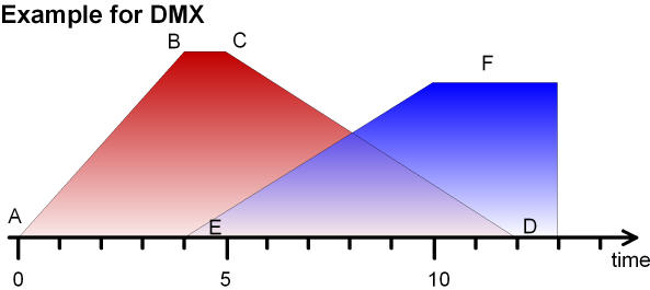
Here three brightness transitions are to be programmed: A->B, C->D and E->F. Thus three virtual switching decoders are needed.
| Decoder | start time | Explanation |
|---|---|---|
| CV880=1 | CV881=0 | ramp up red with a delay of 0s |
| CV882=2 | CV883=5 | ramp down red with a delay of 5s |
| CV884=3 | CV885=4 | ramp up blue with a dealy of 4s |
| CV886=0 | CV887=0 | decoder = 0 means this list entry is invalid |
Decoder instructions
- After the configuration of the DMX decoder it can be used and addressed
like every other decoder with simple accessory commands.
| Key | Effect |
|---|---|
| 1 | Light off; all DMX channels are set to 0. All macros and decoders which are currently running are terminated. |
| 2 | Light on; all DMX channels are set to 255 resp. to the value given in CV554 up to CV557. All macros and decoders which are currently running are terminated. |
| 3 | Macro 1 is called. This is usually the dusk. |
| 4 | Macro 2 is called. This is usually the dawn. |
| 5 | Macro 3 is called. This is usually the dusk, however with slower speed. |
| 6 | Macro 4 is called. This is usually the dawn, however with slower speed. |
| 7 | Watchdog turned off (deactivate) (to be called after a trigger) |
| 8 | Watchdog turned on (activate) |
Note: the CV's used in general like address are described in the switching software.
Wiring (with OpenDecoder2)
- Relay at output 1
Mono-stable relay, 1 opener, 1 normally open contact; With the opener a message can be issued to an feedback system, with the normally open contact the track power is switched. Note: this relay is turned on after power up by default. - Relay at output 2
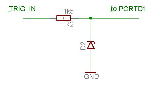
Mono-stable relay, 1 normally open contact; this switches a warning apparatus (horn, lamp, flasher). - Trigger input
Resistance, Zenderdiode: thus an external alarm unit system (emergency stop circuit) can be attached.
DMX is connected to the outputs 7 and 8. On the plate SJ3 is to be left open and SJ4 is to be closed, in order to supply the middle pin with GND (instead of VCC).
To use the watchdog function, the following connections are necessary:
Two inputs can be used for the direct control of the dusk/dawn transitions. The tracers act against ground.
| Tracer | Terminal | Explanation | |
|---|---|---|---|
|
3 | The macro 2 is called (transition to the night, dusk) | |
|
4 | The macro 1 called (transition to the day, dawn), double clicking completely up-steeres the light. |
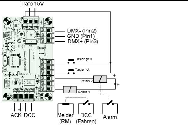
Wiring (with OpenDecoder3)
- Relay 1 (terminals 1 and 2)
The track power is switched. Note: this relay is turned on after power up by default. - Relay 2 (terminals 3 and 4)
this switches a warning apparatus (horn, lamp, flasher). - Relay 3 (terminals 10 and 11)
This relay operates invers to relay 1. It is intended for a feedback system. - Trigger input
thus an external alarm unit system (emergency stop circuit) can be attached.
DMX is connected directly. A XLR connector (female) with 3 pins ist used. (pin 1 = GND, pin 2 = DMX+, pin 3 = DMX-)
To use the watchdog function, the following connections are necessary:
Two inputs can be used for the direct control of the dusk/dawn transitions. The tracers act against ground (terminal 6).
| Tracer | Terminal | Explanation | |
|---|---|---|---|
|
5 | The macro 2 is called (transition to the night, dusk) | |
|
7 | The macro 1 called (transition to the day, dawn), double clicking completely up-steeres the light. |
Watchdog:
- A watchdog curcuit must be addressed cyclically.
If this regular activation is missing (e.g. because of a failure of
the command station or a PC crash), then the watchdog curcuit performs a safety action
- in case of the model course switching the track power off.
- Inactive (SLEEPING): The circuit has no effect, the track power is on.
- Activated (ARMED): The circuit is 'sharp', it watches for missing following activate commands.
- Triggered (TRIGGERED): The circuit has triggered, the track power is interrupted.
- Activation:
With the sending of the activation command (straight, green) the watchdog gets armed. The track power remains switched on (still). If within the response time of the watchdog an additional activation command (straight, green) is received, the response time interval is restarted. The relay for the track power remains switched on during this time and would drop, if no more further activation commands are received. - Release (triggering):
If no more further activation command are received, then the relay is turned off, thus the track power is switched off. The exit 2 is activated for 5s at the same time to e.g. switch a horn or a warning lamp on.
After a trigger, the watchdog must first be switched off once, before it can be activated again. - Switch off:
The the deactivation command (thrown, red) the watchdog is switched off. The relay 1 is turned on, the track power is switched on.
There is an additional trigger input: if LOW is applied here,
then the watchdog is triggered immediately.
One can attach a tracer to this input and implement an emergency stop system.
- OpenDecoder2: Trigger input is Port D1 (pin 3)
- OpenDecoder3: Trigger input is Key3 (connection 14), to be switched against 15 (GND)
Such a curcuit typically has three states:
This decoder uses one turnout address to steer the watchdog.
After power up the watchdog is inactive. The relay for the track power is turned on by default.
Further too:
- back to the general main side
back to the main side of OpenDecoder FAQ
Software download
explanations on the software
config file for TrainProgrammer