OpenDecoder2 (Var. 2.1, without SMD)
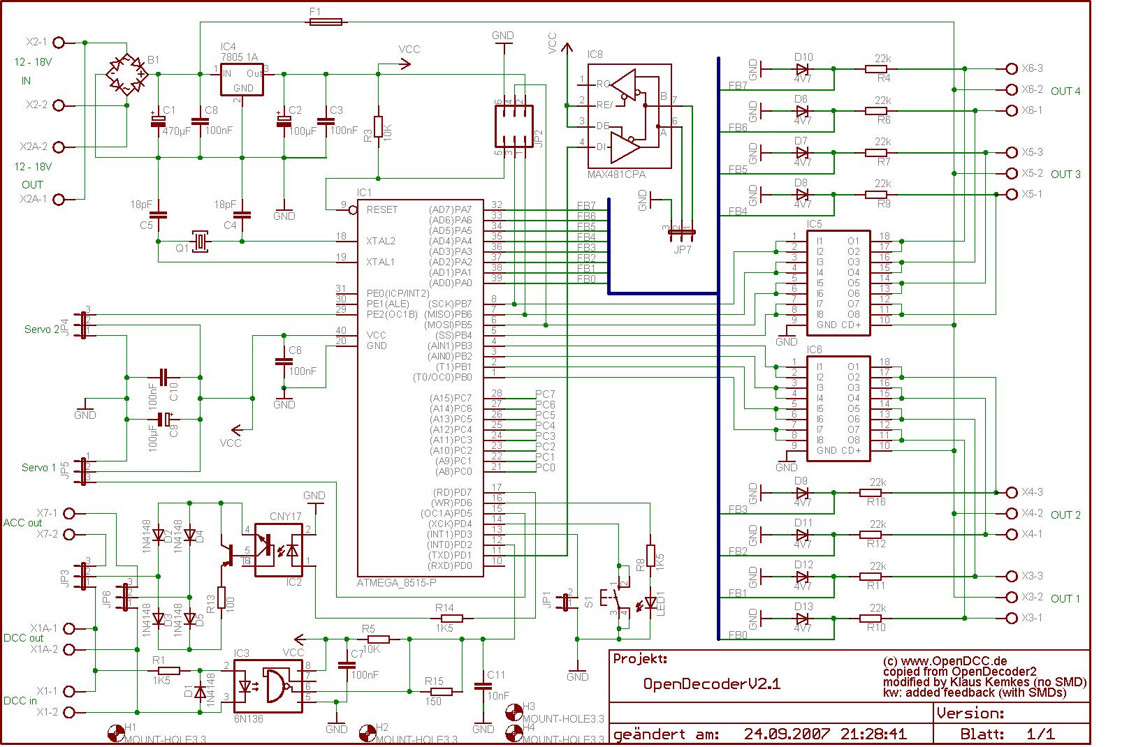
- Schematics:
This decoder is almost identical to the normal Opendecoder2, also based on a Atmega8515 with 8k Flash, 512 bytes of RAM and 512 bytes EEPROM.
Klaus Kemkes has done a copy of the design using DIL chips and one-sided layout. Only the components for the feedback detection are SMD (could be left out). This version is called 2.10, it is slightly larger (80 * 100mm) and is equipped with dual drivers for each output. The outputs are capable of driving 1A. The software is identical to OpenDecoder2. - Circuit description:
(only changes are described here)
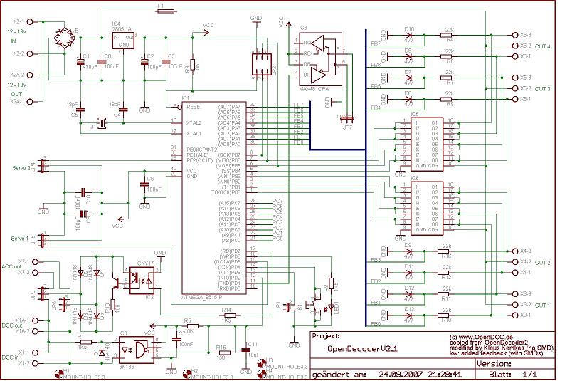
Power supply:
The sockets are doubled; there is also a heat sink for 7805 regulator on the pcb.
DCC input:
Again, the terminal is doubled, the switching between ACK-mode or service mode can be selected via jumper JP3 and JP6.
R15 and C11 are not fitted.
Output:
Here the usual ULN2803 is used (DIL package), so socketing is easy. als DIL Bauform Verwendung, damit er leicht gesockelt werden kann. This driver offers 0.5A continuous current per output and is internally euqipped with a free wheeling diode for inductive loads. Two outputs are used in parallel, this results in lower voltage drop and higher output current.
Turnout feedback:
The outputs of the switches are fed back to the porcessor through a resistors. A Zener diode protects the inputs. These components are SMD and the according connections are on the top side of the pcb. (can be omitted)
DMX:
The RS485 driver is firmly connected to TX, so DMX can only be sent, not received. The port is routed to pin heads. - Layout:
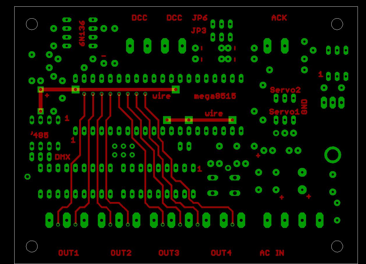
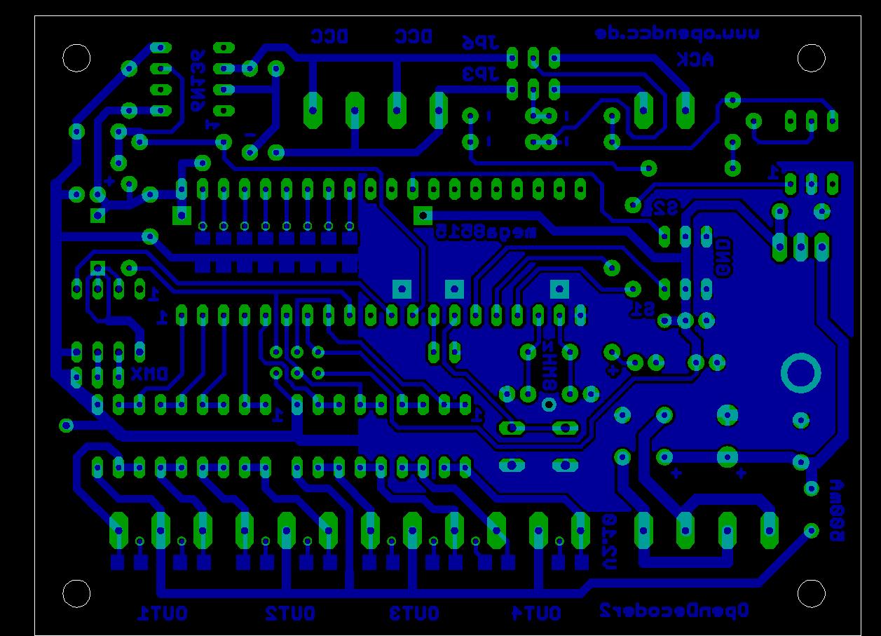
The board version 2.1 is a two-sided pcb with the dimensions 80 * 100mm. It is also possible to use a single-sided pcb and 2 wire bridges. Only DIL package are used (except for feedback). A replica is also possible with hobby equipment. And there is enough space for large screw terminals and fixing holes.
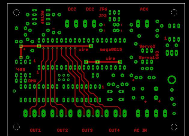
Bauteilseite
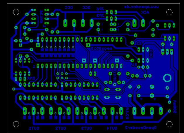
Lötseite
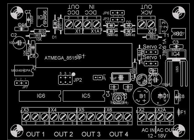
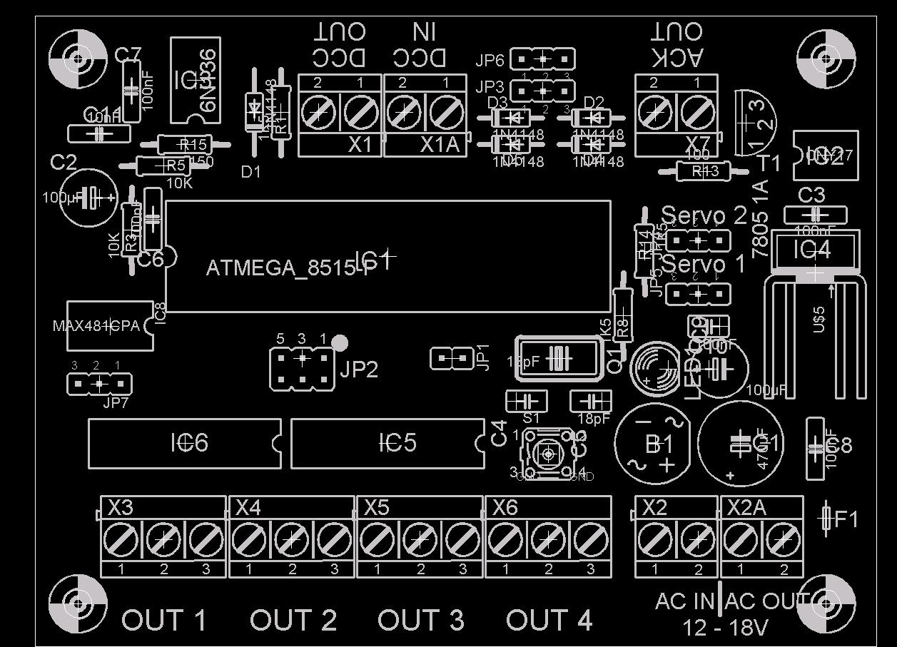
Bestückung
Versions, Change History:
-
Version 2.1:
- 25.09.2007: first publication of this version. It was made by Klaus Kemkes, I don't have PCBs for it!
Documentation
-
Again the Note: This circuit layout and software is free for private use,
commercial use requires the prior written permission.
Schematics / Layout: Download Eagle files
BoM:
Layout:
Data sheets:
-