SignalDecoder: a software for OpenDecoder (Var. 1)
- This software allow for the control of signals,
whereby dimming is used during the change between different aspects.
The characteristics of dimming are adjustable, the brightness over time corresponds thereby
to real bulbs.
Additionally there is a mode for railroad crossing with control of a Faller Car magnet.
This software works as simple accessory decoder, only standard commands are evaluated, neither DCC reset nor broadcast packets are considered. The setup of the operating mode and the address takes place simply by pressing a tracer and sending a turnout instruction. There are the following modes:
| Mode | Function |
|---|---|
| 0 | Four signals with two aspects |
| 1 | Two signals with three aspects, whereby each LED has its own output (no diodes required) |
| 2 | station entry signal and annoucement signal |
| 3 | station entry signal and annoucement signal, with dark palpation |
| 4 | flashing lights (for railroad crossing, pedestrian crossing), additional control of a stop magnet for Faller Car. |
| 5 | each output controlled individually |
| 6 | four signals with four aspects (red, green, yellow, off) |
| 7 | traffic light, with control of stop magnet |
Programming
- The setup of the operating mode and the address
takes place simply by pressing a tracer and sending a turnout instruction. The content
(coil and thrown/closed) of this first received command determine then mode of operation and address.
- After pressing the programming tracer for at least 100ms, the LED is turned on. This indicates that the decoder is ready for the receipt of a programming instruction.
- Send an accessory instruction. The decoder will take its base address from
this instruction according to the following rule:
base address = (sent address - 1)/4. (the remainder is purged)
The decoder is programmed thus to the following addresses: base address * 4 + 1 to base address * 4 + 4
The above 'remainder' is used together with the 'coil' (red or green) to set up the mode of operation:
setting mode of operation 0 2 4 6 Switch 1 Switch 2 Switch 3 Switch 4 1 3 5 7
Modes of Operation
- Generally, OpenDecoder doesn't need any pause between instructions.
This applies also during dimming! (One can find decoders on the market, which are offline
after an instruction for 400ms ;-).
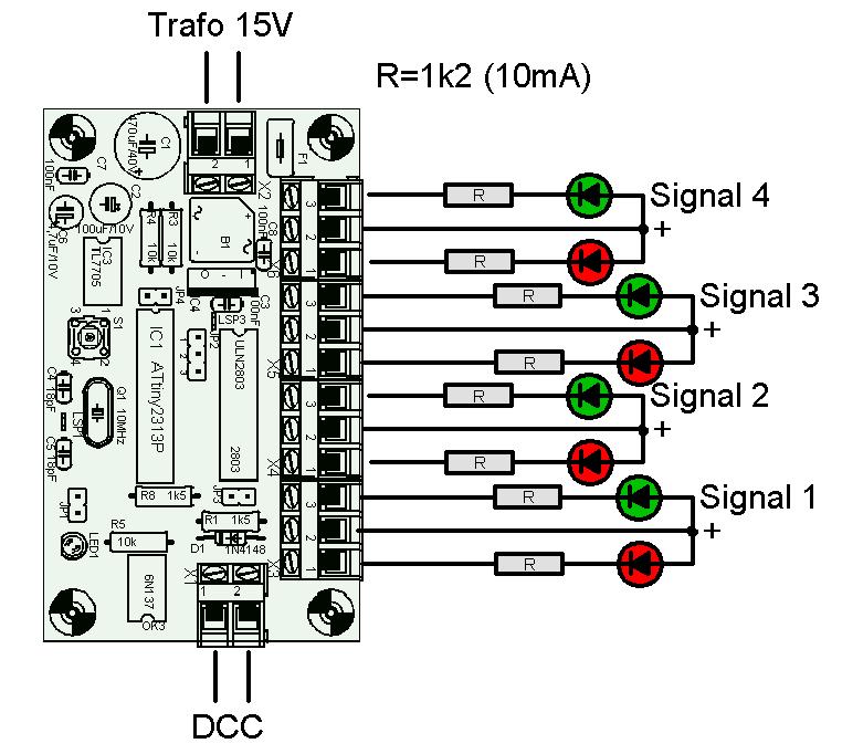
- Mode of operation 0
In this mode four light signals with two aspects are controlled.
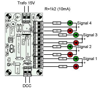
Mode of operation 0: Four signals, two aspects Address Aspect Bright 0 Hp0 - Course stop Sig0 - red 1 Hp1 - Travel Sig0 - green 2 Hp0 - Course stop Sig1 - red 3 Hp1 - Travel Sig1 - green 4 Hp0 - Course stop Sig2 - red 5 Hp1 - Travel Sig2 - green 6 Hp0 - Course stop Sig3 - red 7 Hp1 - Travel Sig3 - green - Mode of operation 1
In this mode two light signals with three aspects each are controlled. The light signals are connected directly (without additional diodes) to the decoder.
Mode of operation 1: Two signals, three aspects Address Aspect on main signal Aspect on announcement signal Outputs 0 Hp0 - Course stop Vr0 - Course stop xxxx0011 1 Hp2 - reduced speed Vr1 - Travel xxxx1100 2 Hp1 - Travel Vr2 - reduced speed xxxx0110 3 reserved reserved xxxx0000 5 Hp0 - Course stop Vr0 - Course stop 0011xxxx 5 Hp2 - reduced speed Vr1 - Travel 1100xxxx 6 Hp1 - Travel Vr2 - reduced speed 0110xxxx 7 reserved reserved 0000xxxx - Modes of operation 2 and 3
In these modes of operation a station entry signal and a announcement signal are controlled. The station entry signal has four aspects: Hp0, Hp1, Hp2 and Sh1. If the announcement signal and station entry signal are mounted at the same location, then the announcement signal is dark while the station entry signal is showing Hp0 or Sh1.
The dark palpation of the announcement signal only takes place in mode 3, mode 2 is intended for two independent signals.Mode of operation 3: controlling main signal and pilot signal Address Aspect main signal announcement signal 0 Hp0 - Course stop Red1 Red2 dark 1 Hp1 - Travel Green shines 2 Hp2 - reduced speed Green Yellow shines 3 Sh1 - station travel Red1 White White dark 4 Vr0 - expect course stop unchanged Yellow Yellow 5 Vr1 - expect travel unchanged Green Green 6 Vr2 - expect reduced speed unchanged Green Yellow 7 reserved unchanged dark
Note: driving a main signal for leaving a station together with an announcing signal with 3 aspects requires four external diodes, because the hardware only has 8 outputs, but 9 different lamps are headed for. Connection in this case is the same as with the switching decoder - Mode of operation 4
Deocder for two flashing outputs and control of a stop magnet, suitable for railraod crossing. Following functions are provided:- St Andrews cross (2 outputs)
- control light at the track: there is a signal (BÜ0/BÜ1) showing to the engine driver
that the St Andrews cross also is flashing. This signal is equipped with a
white light, which begins flashing shortly after the flashing at the crossing.
On these signals there is another yellow point; it replaces the light for 'ready for operation' used in former times. - Stop magnet: This output controls the magnet for Faller Car. This output is activated approx. 2s after flashing and remains switched on 2s longer .
Connection in this case:Mode of operation 4: St Andrews cross, blinking control display for engine driver, stop magnet Address Term Effect 0 - Group 1: turn off blinking, later turn off stop magnet 1 - Group 1: turn on blinking, turn on stop magnet 2 - nichts 3 - nichts 4 - Group 2: turn off blinking, later turn off stop magnet 5 - Group 2: turn on blinking, turn on stop magnet 6 - nichts 7 - nichts 0 Group 1, St Andrews cross phase A 1 Group 1, St Andrews cross phase B 2 Group 1, engine driver light 3 Group 1, stop magnet 4 Group 2, St Andrews cross phase A 5 Group 2, St Andrews cross phase B 6 Group 2, engine driver light 7 Group 2, stop magnet - Mode of operation 5
Each output is turned on-off individually; when switching on or off a smooth dimmed transition takes place. In this mode the decoder uses 8 successive addresses;Mode of operation 5: individual controlled outputs Address Term Effect 0 - output 0 on 1 - output 0 off 2 - output 1 on 3 - output 1 off 4 - output 2 on 5 - output 2 off 6 - output 3 on 7 - output 3 off 8 - output 4 on 9 - output 4 off 10 - output 5 on 11 - output 5 off 12 - output 6 on 13 - output 6 off 14 - output 7 on 15 - output 7 off - Mode of operation 6
In this mode of operation the decoder uses 8 successive addresses; a friend from New Zealand wished this mode :-)Mode of operation 6: Driving R/G search Lights Address Term Bright 0 - Sig0 - red 1 - Sig0 - green 2 - Sig0 - red+green 3 - Sig0 - off 4 - Sig1 - red 5 - Sig1 - green 6 - Sig1 - red+green 7 - Sig1 - off 8 - Sig2 - red 9 - Sig2 - green 10 - Sig2 - red+green 11 - Sig2 - off 12 - Sig3 - red 13 - Sig3 - green 14 - Sig3 - red+green 15 - Sig3 - off - Mode of operation 7
Traffic light
This mode controls a traffic light. The following outputs are provided:
--> identical to the switching decoder, however the lights are softly dimmed on transistions.
links:
Wikipedia - Lichtzeichenanlage!
www.info-lsa.de many pictures and background information
With every mode the outputs for the previous aspect are dimmed down, then the new aspect is dimmed up.
The SignalDecoder evaluates only 'coil on' commands, 'coil off' commands are ignored.
If the jumper is fitted in the respective modes, then the last valid state is stored in the EEPROM.
Adapt to other signal aspects
- See the explanations on the software in
general.
Dimming speed and delay can easily be adjusted with the compile time constants
DIMM_DOWN_SPEED, DIMM_UP_SPEED and DIMM_UP_DELAY.
The ramp and delay are set up for the normal signals with the function set_new_light_val; This function only needs two bit fields: one showing the new state, the other showing the affected outputs. Thus it should be easy to realize a decoder for different aspects.
The examples 'railroad crossing' and 'traffic light' show the configurableness and efficiency of the timing engine as well as the dimmer engine. Further examples are to be found in the effect decoder.
Download/documents:
- The software is available under gnu public license.
If someone should build a new decoder with this software, I would appreciate it publishing here.
And money and/or material donations are welcome; -)
Please refer to download page.
Further too:
- back to the general main side
back to the main side open decoder
to the software explanation
signal bridge special decoder for hidden yard
Special version for Belgium
Advanced Signal decoder for Hardware2