Explanations of the software of OpenDecoder
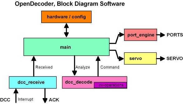
Block diagram of the software
- dcc_receive
Receive the DCC signal (interrupt-driven) and provide the received message. - dcc_decode
analysis of the received message; if service mode or PoM: processing of the corresponding CV accesses - servo_engine
Freely programmable servo controller with time/location mapping - port_engine
Programmable controller for IO (with state machine, including flashing)
Interprocess communication
- OpenDecoder works in cooperative multitasking,
whereby the time-critical parts are outsourced in interrupts.
The message exchange between these modules takes place by means of semaphore operations.
These are done under locked interrupts to make the operation thread safe:
- There are a maximum of 8 semaphore bits, these are defined in config.h, eg C_Received or C_Save.
- The sender of a message, for example, calls semaphore_set(C_Received). The associated semaphore bit is set.
- The recipient of this message calls semaphor_get(C_Received).
The associated semaphore bit queried and reset at the same time.
For example:
if (semaphor_get(C_Received)) analyze_received_message(); - In addition, there is the method semaphor_query(C_Received) for * espionage purposes * , with which the semaphore can be queried, but it is not changed. Parallel to these semaphore operations, which communicate the respective events, the message contents are transmitted via global variables (eg ReceivedAddr). This is not quite clean, but the time conditions are quite relaxed, so no mailbox system is required.
timing control
-
In order to easily adapt the decoder to different applications,
a general time control is provided for each output port. This timing controller uses three variables per output port:
- Port should be permanently on: port = on, rest = 0;
"Rest = 0" prevents further switching of this port. - Port should output a single pulse with 0.5s: port = on, rest = 500ms, offtime = 0;
The "rest" of 500ms causes a switchover and recharge after 500ms, after that no further switching takes place, since "rest" was reloaded with 0. - Port with 1s delayed pulse of 2s duration: Port = off, rest = 1000ms, ontime = 2000ms, offtime = 0
- Change flasher:
Port1 = on, rest = 500ms, ontime = 500ms, offtime = 500ms;
Port2 = off, rest = 500ms, ontime = 500ms, offtime = 500ms
After 500ms each time, reloading will take place, ontime + offtime together make the period of the flashing. - Running light, street light:
Port1 = off, rest = 100ms, ontime = 25ms, offtime = 975ms;
Port2 = off, rest = 150ms, ontime = 25ms, offtime = 975ms;
Port3 = off, rest = 200ms, ontime = 25ms, offtime = 975ms;
Port4 = off, rest = 250ms, ontime = 25ms, offtime = 975ms;
Port5 = off, rest = 300ms, ontime = 25ms, offtime = 975ms;
Port6 = off, rest = 350ms, ontime = 25ms, offtime = 975ms;
Port7 = off, rest = 400ms, ontime = 25ms, offtime = 975ms;
Port8 = off, rest = 450ms, ontime = 25ms, offtime = 975ms;
All 8 ports have the same period of one second, but are started offset by 50ms. The short ontime produces the lightning effect.
| variable | meaning |
|---|---|
| rest | Remaining duration of the current state |
| ontime | Duration of the switch-on state |
| offtime | Duration of the switch-off state |
Examples:
Dimmer Control:
- The dimming control for the crossfading is done with an interrupt-controlled
eight pulse width modulation (PWM) on eight channels. This is implemented as follows:
- There are 60 brightness levels. The desired healing value per port is stored in dimm_val.
- Every 300us there is an interrupt, this switches the dimmer one step further,
after 60 steps it starts again from the beginning. At each stage, the following check is performed:
step action MIN all ports with a dimm_val > DIMM_MIN are switched on. i A port whose dimm_val is less than x is turned off. MAX Restart and message to the DIMMER (C_Dimmstep). - Result: All ports with a dimm_val small DIMM_RANGE_MIN are permanently off, all ports with a dimm_val larger DIMM_RANGE_MAX are permanently on. All intermediate brightness values are output with a corresponding PWM.
- Since the PWM has 60 levels and an interrupt occurs every 300us, this pass is made every 18ms. This corresponds to a refresh rate of 55Hz.
The ramp and delay are set for the normal signals with the function set_new_light_val; This function only needs to pass the bit field of the new states, an adaptation to different signal images should therefore be easily possible.
The way to your own decoder
-
After installing the tools
(AVR Studio, WinAVR and Ponyprog), open AVR-Studio and create a new project.
Select as the simulation environment AVR-Simulator and ATtiny2313 processor.
(accordingly Atmega8515 for OpenDecoder V2).
Now set the clock rate and optimization hints for the compiler under Project->Configuration Options (note in particular -Os = optimize for size): Nun wird unter ProjectConfiguration Options die Taktrate und Optimierungshinweise für den
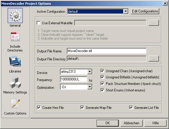
Note: AVR Studio expects the input of the clock rate as a number (without UL), but then sets the entered number with appended UL (= unsigned long).
The original file is then added with a right mouse to the tab Source-File and "add existing source file" to the project and now it will be translated without changing the sourcefile. This can be used to check that the environment is set up correctly.