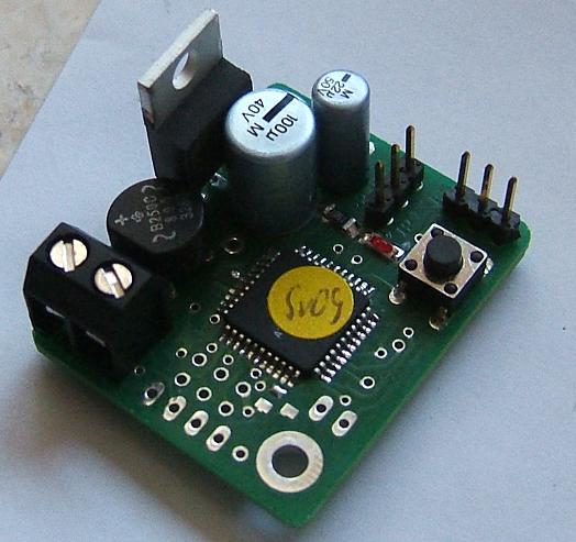
OpenDecoder2 (Var. 2.5, only for servo)
- Schematics:
This decoder corresponds from software point of view to the normal Opendecoder2, also based on a Atmega8515 with 8k Flash, 512 bytes of RAM and 512 bytes EEPROM.
Here, however, change and simplifications are made to specifically optimize the decoder for servos. This version is called 2.5 and is only 32 * 38.5mm large. Only the outputs for servos are available, no normal output port. The servos could be switched off and the decoder is equipped with special filtering, to prevent load peaks of the servo control disturbing the DCC signal.
So this board is ideal for movements applications, like a stop location for Faller Car.
Addtionally, three PWM outputs of Atmega162 are available. This allows to realise an RGB controller with smooth color transistions.
Fuses for Atmega162 - Circuit description:
(only changes are described here)
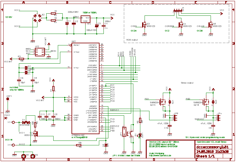
Power supply:
The decoder is powered by the DCC signal, additional series resistors limit the inrush current and dampen load spikes from the servos. A traditional linear regulator (7805 or LM340T) is used, a heaksink may be required if power consumption of the servos is large.
DCC input:
The DCC signel is feed through R5 and the protection zener diode directly to the processor. The current increase for the ACK puls during CV programming is generated with Q2 and R9. Servos should be disconnected during CV programming.
Servo output:
The servos could be turned off by means of a mosfet (Si5903). This allows to completely shut down the servo after a movement. Close solder jumpers SJ1 and SJ2, if this feature isn't needed. Si5903 is not fitted in this case. this ensures no current pulses from the control logic inside the servos (and no noise), but the hold torque of the servos is only the internal magnetic grid of the motor.
PWM output (RGB):
Three PWM channels of the Atmega are routed to pin headers. These signals are driven with MOSFETs BSS123 and can sink up to 100mA. - Layout:
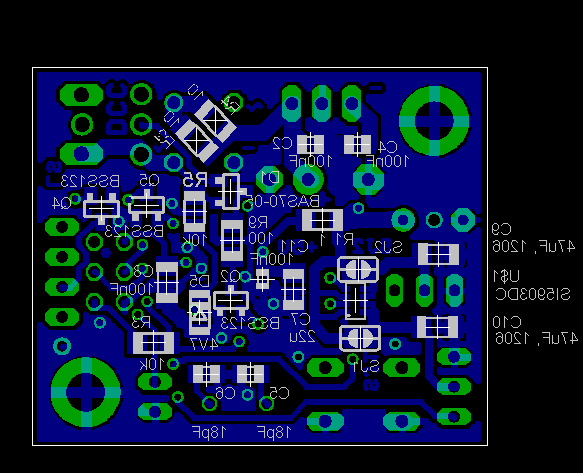
 The board version 2.5 is a two-sided pcb with the dimensions 32 * 38.5mm.
Mainly SMD components are used. Even on this small pcb, large screw terminals and fixing holes are present.
The board version 2.5 is a two-sided pcb with the dimensions 32 * 38.5mm.
Mainly SMD components are used. Even on this small pcb, large screw terminals and fixing holes are present.

Components Solder

Versions, Change History:
- 03.09.2008: Version 2.5: first publication of this version.
- 13.05.2010: Version 2.51: changed ACK curcuit.
Documentation
-
Again the Note: This circuit layout and software is free for private use,
commercial use requires the prior written permission.
Schematics / Layout:
BoM:
Layout:
Data sheets:
-