FeedbackDecoder: a software for OpenDecoder (V.2)
Overview
-
If OpenDecoder V.2 is loaded with
open decoder software,
this decoder offers the possibilty to monitor the actual position
and to do a feedback of this position to the central station and/or
issues an emergency stop.
This software works as complete accessory decoder,
the programming of the decoder can either be done by means of CVs (=configuration variables) or
by pushing a button and have the decoder learn of the next received address as its address.
Theory: Principle of monitoring the turnout position
-
How does it work? Here several processes must interact:
- detecting the position of the turnout
If a turnout is switched, then the desired movement takes place and the coil gets switched off either by the built-in terminal contact or by the decoder itself.- Drives with intrinsic turn off switch:
After finishing the movement the actual coil is deconnected from the power and the coil for the opposite movement is connected to the power. This can be determined in the decoder by a level measurement of the switched off coil contact: the previously activated coil is low (actually openly), the coil for the next movement carries high level.
In this case no additional light barrier, moment tracer a.s.o. is necessary in order to detect the position of the turnout. The terminal switch supplies this information without any additional construction units or lines and is normally mechanically coupled to the turnout.Information on the side drives 40295 and 40296 of Roco line Voltage DC with 12 to 14 V Coil Inductance with metal core: approx. 5 mH
Resistance: approx. 17 ohmsCurrent 500 - 800mA Switching time 10 milliseconds Switching charge 2,5 milli coulombs - Drives without intrinsic turn off switch:
Here the above trick does not function and the software must rely on on an external evaluation circuit - this can be a light barrier, a reed contact or some resonant circuitry, which is detuned by the iron core of the drive.
- Drives with intrinsic turn off switch:
- Communicating the position to the command station
The decoder now knows the position of the turnout, now this information must be transferred to the command station. If the decoder receives an instruction for switching off the coil, then after a delay of 100µs the current position is examined. If this corresponds to the last received turnout command, then the decoder will issue a 3ms long pulse on the ACK line. (= positive acknowledge)
This ACK pulse can be recognized either like a load increase on the DCC line or with a separate token ring line from the decoder(s) to the command station. With every turn off command, the central station reads in the status auf the acknowledge.
Alternatively this ACK can only be activated, if the read back position of the turnout is not correct. In this mode the ACK remains active, until this turnout is again switched (negative receipt). Here all ACK exits can be hooked up to an 'emergency stop' - message.
In both modes of operation the error condition is indicated with programming LED by fast flashing, whereby the number of rapid flashes marks the defective turnout. - Reaction of the command station and the remote control program
If the command station recognizes a missing ACK pulse, then it forwards to the control computer either:- a turnout event, which indicates 'manual' switch of the turnout. Unfortunately the processing of such an turnout event is not supported by Traincontroller.
- a S88 event, whose address naturally is equal to the switch address. By appropriate programming all schedules running towards this turnouts can be stopped.
- Usage with other command stations
Of course this technology can be used also with other command stations. Both the announcement on the decoder itself as well as the possibility of issuing an emergency stop when an error occurs is possible with every system.
Independently of the command station a not functioning turnout is indicated at the decoder: it flashes in the case of an recognized error the LED - whereby the number of the fast flash pulses in a sequence indicates the turnout with the error. Thus the cause of a disturbance can be rapidly located.-
Example: Switch 2 did not switch correctly.
The decoder flashes: __X_X__________X_X_________X_X___
Configuration with CV-variables
-
The desired behavior of the decoder can be configured simply by CV (=configuration variables).
Beyond that the address can be defined also with a programming tracer - this will set the cv's
to reasonalbe values and will select the address of the decoder.
The CV's are used throughout OpenDecoder in accordance with the standardization of the NMRA,
whereby OpenDecoder makes use of the so-called CV-remapping. The CVs are accessable
both at their correct address, and (mirrored) at the address minus 512.
The mirror address is italically indicated in parentheses in the following.
All direct mode instructions (also bit instructions) are supported.
- CV 513 (1): Decoder Adress Low (*=1)
- CV 515 (3): ON TIME Function 1 (*=300ms)
Switch-on time of the output's pair 1. This is indicated in units of 20ms. Thus switch-on time values up to 5s are possible. E.G. a value of 5 corresponds to a time of 100ms, which is sufficient for driving most coil-drives reliably. With programming to 0 the exit remains permanently switched on. If a switching off instruction is received from the command station before reaching the programmed pulse length, then switching off takes place immediately. Additionally the exits switch themselves off mutually always in pairs, so that never two coils or two signal statuses are active at the same time. Warning: If drives without intrinsic turn off switch are used or if the intrinsic turn off switch is defective, a long pulse time and/or eternity time can lead to illegal heating of the drive - in the simple case with innovative deformation, in the bad case with fire risk. - CV 516 (4): ON TIME Function 2
Switch-on time of the output's pair 2. see CV515. - CV 517 (5): ON TIME Function 3
Switch-on time of the output's pair 3. see CV515. - CV 518 (6): ON TIME Function 4
Switch-on time of the output's pair 4. see CV515. - CV 519 (7): Version
This register contains the software version: 0x20; read only - CV 520 (8): Vendor ID (VID)
In this register a characteristic number for the manufacturer is deposited. There is an overview of these characteristic numbers at the NMRA. We use: 0x0D = 13 = DIY decoder.
This register is read only.
On OpenDecoder3: a write to this register will reset all CV (except user curves).
Important Note: This operation lasts longer then a normal DCC write operation. Therefore the acknowledge puls is immediately sent and then the copy of the default settings to the CVs is performed. The decoder will flash during this operation. - CV 521 (9): Decoder Adress High (*=0)
Note: the decoder flashes 5 times if there is not yet an address programmed (but is fully functional). - CV 541 (29): Decoder Configuration
CV 541: DECODER CONFIGURATION 7 Kind of decoder:
0 = Multifunction Decoder - bits 6..0 are used like defined in CV29.
1 = Accessory Decoder.6 Addressing mode:
0 = decoder-referred addressing
1 = outputreferred addressing5 Type of decoder:
0 = Basic Accessory Decoder
1 = Extended Accessory Decoder0..4 reserviert - CV 545 (33): DECODER MODE
This CV specifies the mode of operation of the decoder. Depending on the mode the meaning of the following CV's can change completely!
Important note: be sure to load the correct software, which supports the desired mode!CV 545: DECODER MODE 0 (*) turnout and switch decoder with feedback
(described here)1 dual servo decoder 2 multiposition servo decoder 3 switch and relais decoder (only with Opendecoder3) 8 DMX decoder 16 Light and motor control - CV 546 (34): FEEDBACK METHOD
This CV defines the feedback behavior of the decoder in principle:CV 546: DECODER FEEDBACK METHOD 0 no feedback 1 (*) Positive feedback: If the decoder receives the switching off instruction for a coil and the associated turnout is in the correct position, then a short ACK pulse with 3ms duration is issued.
This is long enough, in order to cover surely the next preamble, however short enough, in order not to collide with the ACK of the next instruction.2 Notification of emergency: If the decoder receives the switching off instruction for a coil and the associated turnout is in the wrong position, then a continued ACK pulse is issued. This pulse remains active until a new instruction for this turnout is received.
Example: Switch 3 did not switch correctly.
The decoder flashes: _X_X_X__________X_X_X_________X_X_X_____ - CV 547 (35): FEEDBACK MODE Funktion 1
This CV specifies the way how the feedback for function 1 (=turnout 1) occurs.CV 547: FUNCTION FEEDBACK MODE 0 Feedback of the last switching command. If the last command before the inquiry has been a switching command for the other side, then an error is generated. Thus the correct receipt the turnout command can be controlled. 1 (*) Monitoring of the turnout position by means of the intrinsic end switches of the magnet drive. Both the previous receipt of the turnout command and the correct switching of the drive are supervised. This setting fits e.g. for the Roco Line drives. 2 Monitoring of the turnout position by an external switch or a light barrier, which is connected to the appropriate 'red' - entrance and in case of the position on 'RED' connects to ground. This can be used e.g. with the Fulgurex motor drives. 3 Monitoring of the turnout position by an external switch or a light barrier, which is connected to the appropriate 'red' - entrance and in case of the position on 'GREEN' connects to ground. This can be used e.g. with the Fulgurex motor drives.
Note: For the settings 2 and 3 the feedback line is to be contacted to the appropriate pin directly on the plate, please see the explanations on the schematicsfor this. - CV 548 (36): FEEDBACK MODE Funktion 2
This CV specifies the way how the feedback for function 2 occurs. - CV 549 (37): FEEDBACK MODE Funktion 3
This CV specifies the way how the feedback for function 3 occurs. - CV 550 (38): FEEDBACK MODE Funktion 4
This CV specifies the way how the feedback for function 4 occurs.
Address assignment:
- There are two different addressing modes for Accessory decoders:
- Decoder-referred addressing:
That is the 'classical' address assignment, which is supported by the majority of the decoders at the market and by the control programs. The address of the decoder is calculated like follows:Address = (CV513 & 0b00111111) + (CV521 & 0b00000111) << 6;
In the address range of 512 decoders there are two reserved addresses: 0 is not used and address 511 is the broadcast address: Instructions to this address go to all decoders. Note: if a lot of switch decoders are used, this can overload the power supply.
Typically 4 output pairs are addressed on one decoder. These output pairs are used to control turnouts or signals (with two aspects).
- Examples:
- Decoder 1: CV513 = 1, CV521 = 0 (switches 1… 4)
- Decoder 63: CV513 = 63, CV521 = 0 (switches 249… 252)
- Decoder 64: CV513 = 0, CV521 = 1 (switches 253… 256)
- Output-referred addressing:
That is the extended address assignment, here a decoder uses only one address. The desired operation is transmitted with the instruction word, the aspect. With the address thus e.g. a signal is specified, the different shown aspects e.g. Hp0, Hp00, Hp1, Hp2 of this signal are specified with the instruction word.
The address of the decoder is calculated here as follows:Accessory-Output = (CV513+(CV521*256)) - 1;
decoder-referred addressing and output-referred addressing. This is differentiated with bit 6 of CV541:
Programming without CV's
- This decoder can be programmed like the other OpenDecoder
also simply by pressing the programming tracer and then using the next received instruction to
learn the address and the mode.
- If programmed as pulse decoder (for switches) then the acknowledge mode for magnet drives is selected (CV547. .CV550=1).
- If programmed as signal decoder then the acknowledge mode is set to 0, i.e. only the last command is supervised (CV547. .CV550=0).
| Mode | Funktion |
|---|---|
| 0 | Switch decoder for magnet drives, pulse duration 0.2s |
| 1 | Switch decoder for magnet drives, pulse duration 0.5s |
| 2 | Switch decoder for magnet drives, pulse duration 1s |
| 3 | Switch decoder for magnet drives, pulse duration 2s |
| 4 | decoder for light signals, 4 signals with two aspects; permanently activated |
| 5 | ??? |
| 6 | ??? |
| 7 | ??? |
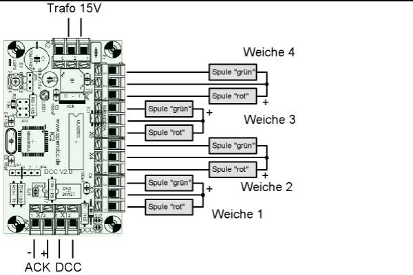
Connection
Explanations concerning the software
-
The software for OpenDecoder2 is written in C (with AVR Studio and winavr)
and is divided into the following modules:
- dcc_receiver.c, .h:
With this module the DCC telegrams are received (interrupt-controlled). By means of a semaphore operation ('Received') it is communicated that a new message is present. - dcc_decode.c, .h:
With this module a received message is decoded; CV-accesses are handled directly within this module, accesses to the decoder are delivered to the main program. - port_engine.c, .h:
This controls the outputs. This is divided into two parts: An interrupt process, which handles time variable operations and a 'action' - program that accomplishes the correct reactions to a recognized DCC command. This module works with a time slot of 20ms. - main.c, .h:
After initializing the semaphore flags of the other modules are queried. If a DCC message is received, then this message is decoded. Calls to the decoder address are passed on as "action" to the port_engine or to the servo process. CV-operations, storage instructions and progamming command are processed within the dcc decode module.