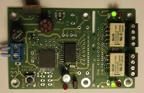
OpenDecoder2 (Var. 2.7, and reverse-loop relay control)
 This decoder corresponds to the normal Opendecoder2,
also based on an ATmega8515 with 8K Flash, 512 bytes RAM and 512 bytes EEPROM.
This decoder corresponds to the normal Opendecoder2,
also based on an ATmega8515 with 8K Flash, 512 bytes RAM and 512 bytes EEPROM.
Here, however, the outputs are routed to a 16-pin connector, and then fed to a relay board with 2 outputs. It is possible to separate the PCBs and mount them standalone. In this case a flat ribbon cable can be used to connect the two boards. (see also HW2, LED).
This version is called 2.7 it comes in two parts (in total 80 x 50 mm), mostly SMD is used.
Schematics
-
(Here only the changes from the normal decoders are described)
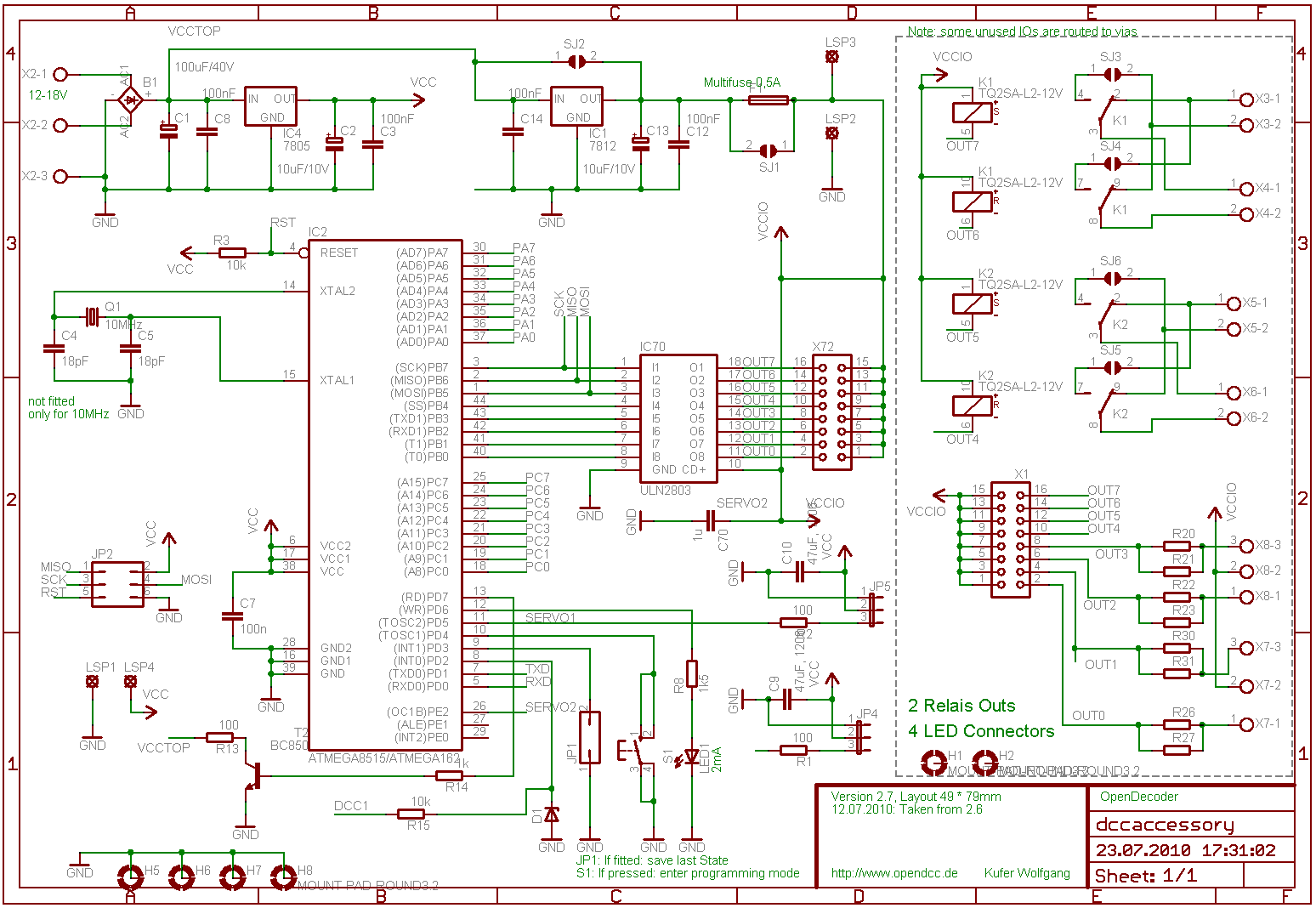
Power supply::
In addition to the 5V regulator, a 12V regulator is provided for safe operating conditions for the relays. When used with a DCC supply of 15V, then you may bypass the regulator (solder jumper).
DCC input:
Unlike normal OpenDecoder2 no optocouplers are used here. The DCC input is fed through a resistor and limited with a Zener diode of 4.7V and connected directly to the processor.
Switching output:
ULN2803 (in SMD package) is used as driver. 4 outputs are connected to terminals. These can be loaded with 300mA (like for LEDs), the other four outputs are used to control the relais. Bistable relais with two coils are used. TQ2-L2 (L2= latching-type, 2 coils) may be used either as SMD or THT variant. These relais are able to handle 2A switching current, when used as reverser the current can be up to 3A as long as switching does not occur under load.
The outputs 0 and 1 resp. 2 and 3 are intended for rd/gn LEDs with commen anode (you can also take two individual LEDs), these LEDs indicate the status of the relais (when using firmware ReverserDecoder). der Schaltzustand der Relais angezeigt. The resistor for the LED can be optionally configured as a through hole or as an SMD resistor 0603.
Control of multiplex signals:
As an option, the outputs of the AVR can be routed to 4-pin headers, this allows for future connection of multiplex signals. ULN2803 is not mounted in this case.
Layout:
- The board (version 2.71) is a two-sided circuit board with the dimensions 49 x 52mm, the relay board is 25x49mm.
Both parts are interconnected and can easily be separated.
After separation, both components can be connected together with a 2.54mm pitch flat cable.
The processor part is identical to version 2.6 (LED control).
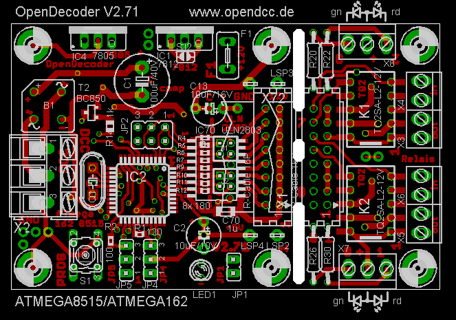
Component side
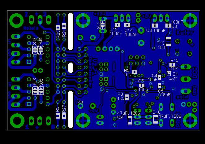
Solder side
Applications
- Reverser:
The decoder is used to reverse the polarity of the track signal in controlled by accessory commands: Close solder jumper SJ3, SJ4, SJ5, SJ6 (beneath the relay) to perform the reversing. Two reversing sections can be controlled. - Motor Switch Decoder:
The decoder is used to reverse the polarity of the motor drives (eg Fulgurex). For this purpose, again all solder bridges (SJ3, SJ4, SJ5, SJ6) must be closed under the relay. Two motor switches can be controlled.
Software
-
Basically any software for OpenDecoder2 can be loaded,
ie for simple relay control, the normal standard software is sufficient.
If you do want complexes reverse switching,
the relay / reverse switching software is recommended.
This software allows for combinatorial evaluation of accessory commands. This sets the polarity according
to the position of adjacent switches.
Versions, History:
- 22.07.2010: Version 2.7: release; sample boards available on request.
- 15.09.2010: Version 2.71: Extension with multiplex connector.