OpenDCC: how to decode DCC?
Principle of DCC reception
-
Wesentlich für einen Decoder ist die Frage: wie kann man DCC dekodieren?
- Measure the pulse durations and compare these pulse durations with the limits specified
in the NMRA Spec.
- Implementation option 1: The pulse duration could be measured, for example, with the capture mode of the timers on the AVR.
- Implementation option 2: The input signal is sampled with a software routine.
- Evaluation: good acquisition of the signal (of course depending on the clock rate
of the sampling), but also great susceptibility to interference when implemented
with capture mode - short signal errors and reflections can mess up the
measurement.
The capture mode causes low CPU load.
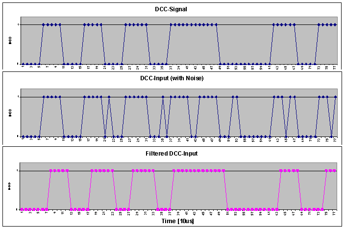
A possible better way is to use sampling (e.g. with 100kHz) with additional filtering - here unfavorable reception conditions (e.g. short signal interruptions due to dirty tracks) can be compensated.
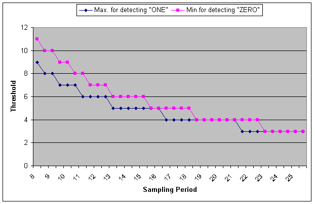
Calculation of the necessary sampling rate A = max. samples at detection 1: 64µs / Period + 1 B = samples at detection 0: 90µs / Period Condition to distinguish 0/1: A < B Result (aus Delta): Period < 13µs
Now the condition "N = natural number" at one of the two limits must also be taken into account. This can result in similar fractional parts at both limits, so that beyond the above condition further period values can be found, which allow a clear distinction.

Here it can be seen that at sampling intervals of up to 15µs, a clear distinction 0- 1 is always possible. In the range 17-18us and at 22us there are windows that also allow a distinction. At small sampling intervals, the difference becomes larger and larger, which increases safety. - Filter:
A significant improvement in reception, especially with mobile receivers (where the wheel-rail contact is a considerable uncertainty), can be achieved with a suitable low-pass filter, whose impulse response should have about the width of half a "one".
The low-pass filter should have an odd length due to the symmetry of DCC to increase interference immunity, e.g. be 3, 5 or 7 long. The integration time should not be greater than the minimum half-period of a "1" (about 50us). Therefore, the following alternatives arise:-
Filter Length 3, Period ~ 17µs
Filter Length 5, Period < 11µs
Filter Length 7, Period < 7µs

Result: Short signal interruptions are filtered away.
The scanning method can mean too much temporal uncertainty for BiDi (RailCom) and is not usable, at least in the 22µs variant..
- Setting an average pulse duration between 1 and 0 and targeted sampling of the input
signal.
- Implementation possibility: The DCC signal starts the scanner (e.g. by edge triggering). This samples the signal after 1.5 pulse durations of a "1" and thus detects whether there are fast level changes (the polarity has changed) or slow level changes (the polarity has not changed). This can be done with the interrupts and timers of the AVR. Advantage: low software effort.
- Evaluation: relatively reliable evaluation (measurement in the middle of the eye),
but only a signal evaluation is carried out. If this is disturbed, a wrong bit is
detected (but DCC has a checksum for that :-) If the sampler is not properly
implemented (e.g. because the first interrupt, which starts the sampling interval,
is only processed with a delay or because the switching delays for the forward
and back edges of the input signal are not the same), malfunctions can also
occur.
For RailCom, a edge detection is also required to ensure the time reference for the returned data (but this is possible)
- Direct edge triggering, time comparison
- Realization: The DCC signal generates an interrupt, in which the current time (circular) is taken and compared with the previous time. In this way, the ISR detects whether there are fast or slow level changes. Advantage: low software effort.
- Evaluation: relatively simple, confident in decision-making. Problems with
reflections and disturbances.
Well suited for RailCom, as there is already a hard signal edge reference.
- FM demodulation e.g. by sliding DFT or correlation
- Realisation possibility: Sampling of the input signal e.g. with 14.5us (this is 0.125 * total duration of a "1"). These 8 values are now correlated with the corresponding pulse sequences for "1" or "0" and, depending on the deflection of the correlator, the decoding takes place.
- Rating: Safe decoding even with massively disturbed signals, but requires *some* computing power ;-) . Less suitable for railcom. Such an algorithm is like breaking a butterfly upon a wheel, at least when it comes to signal decoders; in the case of locomotive decoders, where there is interference from the wheel-rail contact and from the motor, it could be quite useful.
Essential for a decoder is the question: how can you decode DCC? DCC is basically FM: a "1" is encoded with two short pulses (nominal 58µs each), a "0" with two long pulses (116µs each). A decoder must interpret pulses between 52µs and 64µs as "1", pulses between 90µs and 12ms as "0".
This results in the following possibilities for decoding:
Realization of DCC reception (according to method 2):
-
The applied DCC signal triggers interrupt 0 of the AVR. In the interrupt service routine for this
interrupt, only timer 1 is started.
This timer 1 is programmed as follows:
| Programming Timer 1 | ||
|---|---|---|
| Mode | CTC | Clear Timer on Compare Match: when the CompA count value is reached, an interrupt is triggered and the timer is reset to 0. |
| CompA | 87µs | Comparative value for CTC mode |
Now the read bit is evaluated. For this purpose, the ISR uses a status variable Recstate. Recstate describes where the ISR is located in the DCC protocol.
| Recstate | State of ISR |
|---|---|
| WF_PREAMBLE | wait for the complete receipt of the preamble (at least 10 times "1") |
| WF_LEAD0 | wait for the first "0", which indicates the beginning of a message. |
| WF_BYTE | wait for the complete receipt of a byte. In this state, 8 bits are left for each. |
| WF_TRAILER | wait for the final separation bit of a byte.
If this is "0", another byte follows - the state goes back to
WF_BYTE. If this separation bit is "1", then a complete message is received. |
Realization of DCC reception (according to method 1):
-
The timer is programmed to trigger an interrupt every 10us. In the interrupt service routine for
this interrupt, the applied DCC signal is read in and inserted into a low-pass filter of length 5.
The output of the filter can now assume values from 0 to 5, with 0,1,2 indicating a "LOW", the values 3,4,5 showing a "HIGH". If the filter output changes polarity, a zero crossing of the DCC signal is detected. You can either evaluate only one polarity change or, as here, both directions. If the time since the last polarity change is <70us, then half of a DCC-"1" has been detected.
This half-bit recognized in this way is now evaluated. For this purpose, the ISR uses a status variable Recstate. Recstate describes where the ISR is located in the DCC protocol.
| Recstate | State of the ISR |
|---|---|
| WF_PREAMBLE | waiting for the full receipt of the preamble (at least 20 times "half-1") |
| WF_LEAD0 | wait for the first "0", which indicates the beginning of a message. |
| WF_SECOND_HALF | waiting for the corresponding second half-bit. This must have the same value as the first half-bit. |
| WF_BYTE | wait for the complete receipt of a byte. In this state, 8 bits are left for each, with the state WF_SECOND_HALF additionally activated after each bit in order to control the second half-bit.. |
| WF_TRAILER | wait for the final separation bit of a byte.
If this is "0", another byte follows - the state goes back to
WF_BYTE+WF_SECOND_HALF.
If this separation bit is "1", then a complete message is received. |