Signal Bridge (based on OpenDecoder1)
In a hidden yards simple signals are needed for the indication of the status of the track, e.g. if schedule is ready for run, but because of contact problems the locomotive doesn't start. Or because the layout is operated with an video car and one must know and see the current signal state.
These signals are arranged as a brigde above the hidden yard. Typically, a simple contruction is choosen (simply LEDs). This PCB contains 4 signals and is very simply.
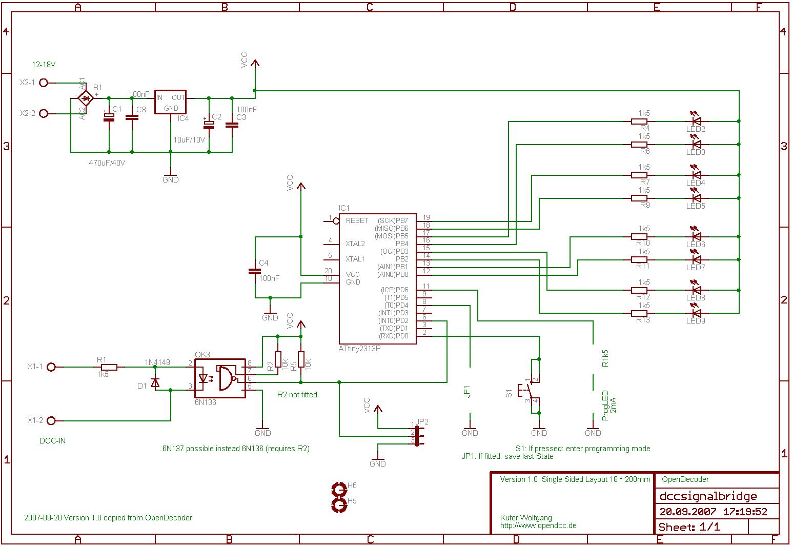
- Schematics:
This decoder is similar to Opendecoder1, also based on a Attiny2313. The outputs are directly connected to LEDs. - Description:

The LEDs are directly controlled by the processor, low current LEDs are accordingly required. For PCB-space reasons both the programming LED and the Speicherjumper were removed. The Atmel Attiny2313 is operated with internal reset generator and RC oscillator.
A second PCB can be attached by means of three wires (as a slave decoder); this second device doesn't require neither power supply nor DCC receivers. - Layout:
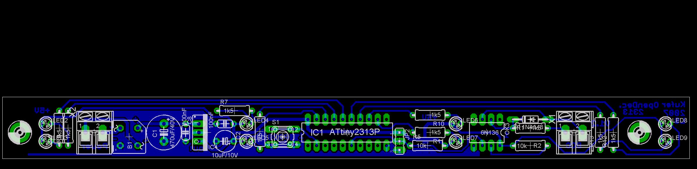
The plate is a narrow stripe 18*200mm in size. Only DIL components are used, the layout is one-sided, without any cable links.

Versions, changes:
-
Version 1.0:
- 25.09.2007: first publication;
Software:
-
The software is based on the Signaldecoder
(thus with bulb simulation and smooth switching), here however
the mode 'four signals with two terms' is fixed. Additionally there are two new features:
signal 1 'green' flashes as a control display as long as the decoder is not yet programmed to an address.
While the decoder waits for an programming address, both LEDs for signal 1 (red and green) are simultaneously on
(and dimmed to 50% duty cycle).
Dokuments:
-
The software is available under gnu public license.
Schematics / Layout: download eagle files
Source code: Signalbridge Decoder (.hex, .eep and .c file)