OpenDCC - Command Station for DCC - Details on the Software
- OpenDCC can be loaded with different software. Here you will find the description
of a versatile software, which is configurable to different modes by means of jumpers.
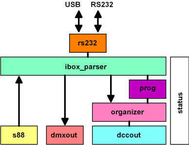
- HARDWARE.H: Initialising of the processor and the ports
- CONFIG.H: Initialising of the operating modes, memory size, etc.
- DCCOUT.C: Generation of the DCC-protocol (DCC Encoder)
- DMXOUT.C: Generation of the DMX-protocol (DMX Encoder)
- ORGANIZER.C: DCC command engine (priority, repeat, refresh)
- LENZ_PARSER.C, IBOX_PARSER.C: Translation of PC-commands to suitable internal calls.
- LENZ_PROGRAMMER.C, IBOX_PROGRAMMER.C: Processing of programming commands
- RS232.C: Interface to the PC (with interrupt + fifo controller)
- STATUS.C: State management, Timertick, Keys and LEDs
- S88.C: Evaluation of the external feedback circuit.
- MAIN.C: Init, Loop
| Jumper / Mode of Operation | ||
|---|---|---|
| JP2 | JP1 | Mode |
| open | open | Operation as command station, the command set is emulating the Intellibox ® from Uhlenbrock. The command set can also be changed to Lenz-emulation (this is defined in a #define in config.h, requires recompile) |
| open | closed | Use as DMX controller, control by means of keys
(Remote Control not yet enabled)
(Note: This is depracted, please realize the DMX control with the DMX decoder.) |
| closed | open | Operation as HSI88 interface, command set is compatible with Littfinski |
| closed | closed | Test operation: All LEDs flash, all data on the interface is send back with 19200 baud. |
When no jumper is equipped, the box will operate as DCC command station. Commands are translated from the PC to DCC, whereby OpenDCC (depending on the choice) will emulate either a Lenz command station or an Intellibox ® (default). Not all commands according to Lenz V3.0 or IB are implemented. E.g. there is no support for 27 driving steps and no support for multi traction commands.
The software is written in C using WinAVR (based on avrgcc) and simulated by means of AVR-Studio (available at www.atmel.com).
All is freely available as open source under the GNU license.
During the development special attention was paid to maximise the throughput of DCC commands; moreover, an intelligent refresh algorithm is also implemented which priorizises new speed commands and then cyclically repeats them. The repetition rate of commands for locomotives which haven't been used for a longer period is decreased. The algorithm also distinguishes between functions, acceleration and braking: brake commands have top priority.
The software comprimises different modules:
DCC generation
-
The module DCCOUT generates the rail signals.
- How does a DCC signal look like?
In the case of DCC the rail signal is a constant voltage signal, but with alternating polarity. The information to the locomotive/turnout is encoded by means of the polarity changes.
The coding rules are very simple: two polarity changes with a 58µs space means a '1', two changes with 116µs space means a '0'. Because there are always two symmetrical polarity changes, the output signal is free of DC voltage and the polarity at the receiver side is without relevance. A '1' lasts two times 58µs = 116µs. a '0' is double in time.
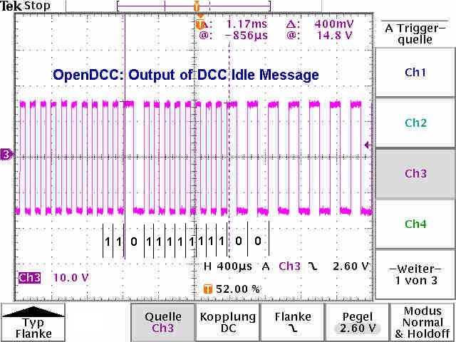
In this way a serial bit stream is sent to the locomotive. To allow for an evaluation of these bits in the receiver, the data stream must be subdivided. With DCC this happens by subdivision in preamble, databytes and checksum. The preamble marks the beginning of a new message. Preamble, databytes and checksum (8 bits) are separated by a 0 of each other.
In order to allow for the recognition of the preamble by the receiver, it must be built up according to a rule which does not apply in the normal data stream. With DCC the preamble is characterised by at least twelve 1 bits. Because the data bytes are separated after 8 bits by "0", this long "1" sequence does not appear in the normal data stream.
The message (after the preamble) contains two to five data bytes (separated by 0), which typically contain the address and the speed step for a locomotive. The original DCC format intended only 2 data bytes, this was extended later up to 5 data bytes. An 8 bits XORed sum of these data bytes is added to these data bytes as a checksum. If the receiver forms now the XOR of all received bytes, the result must be 00000000, only in this case the message is valid. - What is the meaning of the single bits?
The first byte distinguishes between locomotive command, accessories decoders and program commands (service mode). The following bytes are encoded according to their groups differently.
In principle, a DCC message always begins with one (or two address bytes) followed by one or more data bytes in which the respective action or locomotive speed is encoded.First Byte 0: 00000000: Address 0 is reserved as broadcast for all locomotives. 1-127: 0AAAAAAA: If the first byte starts with a 0, then it is a locomotive command with short address. 128-191: 10AAAAAA: The range (128-191) (including) is reserved for accessories decoders. 192-231: 11000000-11100111: This is the header for a locomotive command with long address, the other address bits will follow in the next byte. 232-254: 11101000-11111110: This area is reserved for extensions. 255: 11111111: nothing is addressed (IDLE).
The DCC protocol has been extended in the course of the years over and over again; unfortunately, different representations have been set up for the speed (14.27, 28 and 126 driving steps). For more information on the encoding of the data bytes see NMRA. - Example 1: drive command to lok 5, drive step 4(of 14 steps), forward.
A command with 3 bytes is sent:Preamble Startbit Addressbyte (=0AAAAAAA) Startbit Databyte (=01DCSSSS) Startbit Checksum StopbitIn this case address byte AAAAAAA [A6..A0] is the locomotive address and in the databyte D [Direction], C[[light function], SSSS [speed]. The DCC telegram is composed as follows:address byte = (Loco address & 0x7F); data byte = 0b01000000 | (speed & 0x0F) | (direction bit << 5); Checksum = Addressbyte ^ databyte;The direction bit is one for forward and zero for backward.Preamble 0 Addressbyte 0 data byte 0 checksum 11111111111111 0 00000101 0 01100100 0 01100001 - Example 2: DCC command for turnout drive
A command with 3 bytes is sent:Preamble startbit address byte 10AAAAAA startbit data byte 1AAA1BBR startbit checksum stopbitHere the address byte AAAAAA [A5 .. A0] and the data byte AAA [A8. A6] results in the address of the turnout, whereby the addresses A8 to A6 are transferred inverted. BB is the local address in the decoder (0,1,2,3), R is the output bit, i.e. which coil should be activated. The code for this:address_byte = 0x80 + (address & 0x3F); Data_byte = 0x80 + (address / 0x40) ^ 0x07) * 0x10; checksum = Addressbyte ^ Databyte;
The address 0 is reserved as a broadcast, so that the first turnout group starts at address 1.
Unfortunately, with the PC protocols there are small, but annoying differences in the address area, and in the interpretation of the output bit as well as the activate bits (in the above example the 1).
Uhlenbrock (Intellibox) describes as follows (and also sent this):
'r' (red = thrown) and ('r' may be specified as '0')
'g' (green = closed) and ('g' may be specified as '1') The address area in the PC interface starts (opposite to the documentation) with 1. Thus the first decoder maps to addresses 1... 4; moreover, the Intellibox also never sends the switch off command on the rail, even if this is requested from the PC.
Lenz describes the directionbit as D2 with following text:
D2: D2 = 0 means output 1 of the turnout selected.
D2 = 1 means output 2 of the turnout selected.
Indeed, nowhere we can find out what signifies output 1 or 2. Examing a log file it looks like red and green are exchanged. OpenDCC has a special CV to cope for this inverting (switchable).
But with Lenz turnout addresses start with the address 0 and the switch off command exists (at least sometimes). - General rules for the packets
- Preamble: A receiver must recognize the preamble from at least 12 '1's, a preamble with less than 10 '1's must be rejected; a controller must send at least 14 '1's. The stopbit may be included in the preamble of the next command. When the controller is set in programming mode, the preambler must be at least 20 bits long.
- Length: Such packets could have 3 to 6 bytes of length, but with all packets the last byte must be the XOR checksum of all preceding bytes.
- Distance between packets: Packets addressing the same decoder must have 5ms time gap. At least any packet must be resent after 30ms in DCC, to prevent decoders switching over to analogue operation.
- How are these bits generated in OpenDCC?
The timer 1 is used, this is operated in the CTC mode (Clear timer on compare match), after reaching the compare value the timer begins again at zero. At this time the DCC bit is switched by means of hardware. The outputs of the comparators are connected to the booster and thus generates the rail signal.
This timer overflow also generates an interrupt, the interrupt routine updates the compare values of the next bit, according to which whether 0 or 1 should be sent. Every polarity change of the DCC signal generates an interrupt, every second interrupt advances by 1 bit within the DCC message.
Starting with the preamble the interrupt routine handles bit per bit of the DCC message and also handles the overhead of the DCC protocol (so to speak, Layer 1). This means that the preamble and the checksum (XOR byte) is calculated inside the ISR.
The 'next higher level' program only has to assemble only the data bytes and hand these over to DCCOUT (in the data array 'next_message'). The handing over is done by means of a semaphore ('next_message_count'). DCCOUT takes over the message only if this semaphore is greater than zero and decrements this semaphore by 1 every time a message is sent.
S88.C, reading in of the occupancy detectors
-
n S88.C the occupancy detectors are read in and supervised on any change. There are three S88-streams;
these are read in "in parallel". If a strema is shorter (i.e. has less bits), then, indeed,
this stream also is clocked in, nevertheless, these bits are no more evaluated.
Up to 1024 occupancy detector inputs are supported; however, these are not available in all interface formats. If the HSI88 mode is activated, only 31*16 = 496 inputs can be scanned. More is not possible according to the description of the HSI88 and also PC control programs are limited to this value, if HSI88 is chosen.
There are 2 data arrays, s88_data and S88_change. If a change is detected during the scan of the S88 bus, this bit is copied to s88_data and the corresponding bit in the s88_change is set. When this new data bits are send to the PC, the change flag is cleared.
The notification of the PC occurs according to the protocol either in nibble mode (Lenz), byte mode (Intellibox) or as 16 bit values (Littfinski HSI88).
STATUS.C, Timertick and status administration
-
In status.c the LEDs are driven, keys and external inputs are scanned and the status of
OpenDCC is administered.
The LED control is timer-driven and utilizes a structure led_pwm. This contains for every LED the 'remaining time' in the actual state, the switch-on period and the switch off period. If the remaining time is set to zero, this state is preserved forever. Thus different flashing modes can be generated quite easily:
  LED_RS232_OFF;
     led_pwm.rs232_rest = 20000L / TICK_PERIOD;
     led_pwm.rs232_ontime = 50000L / TICK_PERIOD;
     led_pwm.rs232_offtime = 150000L / TICK_PERIOD;
break; |
Another use of the timer is the debounce engine for the keys and as a time-out counter for the programming task.
ORGANIZER.C, Locomotive and command administration
-
It is up to this module to provide for low latency timing and high data throughput for locomotive
commands, as well as to organize the refresh of the already moving locomotives.
The sophisticated implementation of this module is one of the
main advantages of OpenDCC compared to commercially
available controllers!
The actual limit is the throughput on the rail - DCC has an average of about 4000 - 5000 bits/s or about 100 messages/s. Therefore in OpenDCC a set of rules is defined which garantiees that new telegrams are put out fast and are later on sorted with lower priority into the general refresh.
Brake commands (i.e. commands with which the speed is reduced compared with the actual speed) are executed with top priority on the rail, while in parallel an acceleration command to another locomotive must wait a small time.
| Set of rules of the organizer |
|---|
For locomotive commands: loco speed is stored in the loco memory.

Scan all queues and buffers of the loc, if an old command of
this loco is still waiting - if yes, exchange and process this.

Speed higher or lower than the current driving speed?
-        if lower:  put command in the high priority queue.
-        If higher: (or function or accessory): put command in low priority queue.

When a command in a queue is executed, then this is command stored in the repeat buffer:
    Speed commands with 3 repeats, accessory commands with 2 repeats.
The output to the rails occurs in the following order:
   1. High priority queue.   When this queue is empty:
   2. Low priority queue.    When this queue is empty:
   3. Repeatbuffer.          When this queue is also empty:
   4. Refresh loc memory. (in each case in the sequence:
             Speed, funct1, speed, funct2, speed, funct3, speed)
|
In addition, the ORGANIZER follows a few more additional rules as for example no command twice to the same locomotives, priority to broadcast command, a.s.o.
Anzahl von Lokomotiven und Lokformat
OpenDCC is able to address up to 9999 (Lenz parser) or 10239 (Intellibox parser) different locomotives. However, these cannot run at the same time. The number of locs running at the same time is limited (with the current SW version) to 64 (storage space in the locomotive memory), more locomotives are really not sensible with the DCC protocol. A DCC message lasts about 8-12ms, depending on address and speed steps, i.e. with 10 or more simultaneously braking locomotives it starts to become interesting. However, more locomotives can absolutely exist; the locomotive memory and repeat buffer are adapted in case of place problems by stripping out the 'oldest' locomotive. This 'oldest locomotive' is no more refreshed.
OpenDCC can address the locomotives with DCC14, DCC28 or DCC128. This is fixed in the case of the Lenz protocol simply by the driving command from the PC. In case of the IB protocol there is no command which defines the format. Hence, two additional commands were defined, which permit the handing over of a locomotive format from the PC to OpenDCC:
| P50X-ASCII | LS {Lok#, [Format], [Steps]} only "2" (=DCC) is allowed for Format. |
| P50X-BINARY | 0x86: XLokCfgSet - length 1+3; byte1+byte2 = addr, byte3 = format |
Some PC control programs even don't store the locomotive format, but request this format info from the command station. OpenDCC supports this by stored the format for a certain locomotive into the EEPROM return this value at the next query of the PC program.
If a locomotive has never been controlled before, the format DEFAULT is send back. OpenDCC works with DCC28 as a default setting (this is changeable by a CV). To change a locomotive to another format, it is sufficient to call this locomotive once in the desired format. OpenDCC supports a maximum of 64 locomotives with a format deviating from the default setting.
Internally all speeds are stored in the DCC128 format. Speed commands are always converted inside the parser to this format. The same conversion also occurs at the rail output side depending on the format currently selected for this locomotive. (Routines: convert_speed_to_rail () and convert_speed_from_rail ()).
If Intellibox®-Parser is used, no conversion on the parser side is necessary, P50X delivers always 0 .. 127 speed steps. The MSB denotes the direction setting.
| Summary of the functional commands of the ORGANIZER |
|---|
init_organizer(void) organizer_ready(void) do_loco_speed_f(addr, speed, format) Set speed and format of a locomotive do_loco_speed(addr, speed) Set speed of a locomotive do_loco_func_grp0(addr, funct) Light function do_loco_func_grp1(addr, funct) Functions f1-f4 do_loco_func_grp2(addr, funct) Functions f5-f8 do_loco_func_grp3(addr, funct) Functions f9-f12 do_accessory(addr, output, activate) Turnout command do_all_stop(void) Stop command |
RS232.C, Control of the serial interface
-
OpenDCC operates the serial interface with 19200 Baud (this is also default with Lenz V3.0).
This rate can be changed with the command BAUD (0xF2). 38400, 57600 and 115200 Baud can be used.
The default may also be changed compilation to another value. (init_rs232 call in main.c)
The data format always is 8 databits, no parity and 1 stopbit (8n1).
The whole communication is interrupt driven and is buffered with Fifos (depth 64 bytes). Five bytes before the input fifo gets full, PC commands are stopped by hardware handshake.
If OpenDCC receives a BREAK (i.e. Rx is for a long time at +12V, or '0' is permanently received), then the UART is reset automatically to the default (19200 Baud). See also the comments in ISR (SIG_UART_RECV).
MAIN.C, main program
-
There are 4 interrupt routines:
- DCC counter: This interrupt triggers the reprogramming of the counter 1. Thus the sequences for DCC-0 and DCC-1 on the compare outputs of this counter are generated.
- Timer tick: This interrupt controls keyboard and timeouts.
- UART Rx: received byte is written into fifo
- UART Tx: byte in send fifo is transmitted.
int main(void)
  {

    init_main();                       // all io's
    init_dccout();                     // timing engine for dcc
    init_organizer();                  // engine for command repetition,
                                       // memory of loco speeds and types
    init_rs232();                      // isrs+fifos from/to pc
    init_interrupt();
    init_tick();                       // 5ms timer tick
    init_programmer();                 // dcc programmer
    init_parser();                     // command parser

    set_opendcc_state(RUN_OFF);        // abgeschaltet

    while(1)
     {
       run_state();                    // check short and keys
       run_organizer();                // let run command organizer
       run_parser();                   // check commands from pc
     }
  }
|
Unterlagen / Links
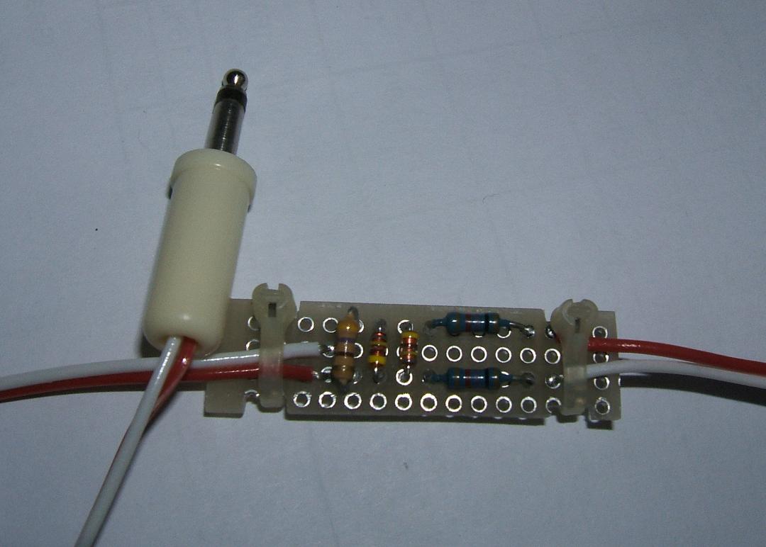
Protocol and analysis of the track signal: with ShowDCC and a small adapter for the soundcard: