OpenDCC Z1 - Command Station mechanical details
- Dimensions: base board 100 * 120mm, S88-board: 38 * 75mm, front panel board: 38 * 23mm.
(all boards are laid out on a single 160*100mm standard board ("Europa-format") and need to be separated prior to assembly and soldering. There are dotted lines on the board showing where there have to be cuts.) - Mounting holes:
Base board (seen from front top, (x,y[mm])):
one hole each at: A(4.5, 4.5), B(95.5, 4.5), C(4.5, 85), D(66, 85) und E(95.5, 85);
attachment to Teko-cabinet : T1(4.5, 22), T2(95.5, 22), T1(4.5, 98), T1(95.5, 98)
S88-board: one hole each at C'(7, 3) und D'(63.5, 3);
The S88-add-on-board is mounted on top of the base board connecting C and C' and D and D', respectively, keeping a vertical distance of 15mm by use of a spacer bolt. Three RJ45-jacks (connectors for S88) are positioned at 15mm, 35mm and 55mm; after mounting with an offset of 2.5mm they will move to 17,5mm, 37,5mm and 57.5mm, respectively.
Front panel board: hole located between the two push-buttons , distance to (imaginary) bottom is 7,5mm. As a result, the front panel board can be mechanically attached with the base board using a mounting cube (Buerklin, Best.Nr. 17H912). Electrical connection is established by two angled 5-pin connectors Fischer SL (Buerklin, Best.Nr. 59F8228).
Both push-buttons are located 13,34mm (=7,5mm + 5,84mm (230mil)) above the base board (centerline of button-chassis); the LEDs are situated additional 400mil above at 23,5mm (=7,5+16(630mil)) above base board level, distance between push-buttons (center-to-center) calculates to 22,86mm (900 mil) with both buttons evenly distributed on the front panel center board.
Left and right of the front panel center board there are attached additional LED-boards, in a way that solder-connects respective onboard-printed labels A-D and ensures that the back panel grid can be additionally reinforced by a rail. The two additional LEDs located on those side-panels follow the same 22.86mm grid as do the other on the front panel center board.
Positions of the LEDs (centers) are therefore : 15,71mm, 38,57mm, 61,43mm, 84,29mm. - Cabinet:
In case the base board is intended to be used with the soldered plugs and connectors, a cabinet with 120mm length is required. Adequate cabinets are, for instance, the aluminum-cabinet type AKG 105 46 120 SA of Fischer or the Teko Cab 022 cabinet (Buerklin 60H304 or Reichelt); Note that Reichelt mentions an incorrect mounting hole-offset of 86.4 mm. The information given by Teko's website (Teko.it) is correctly stating 91mm; mounting height offset within the cabinet is 4mm.
Frontcover, backcover:
-
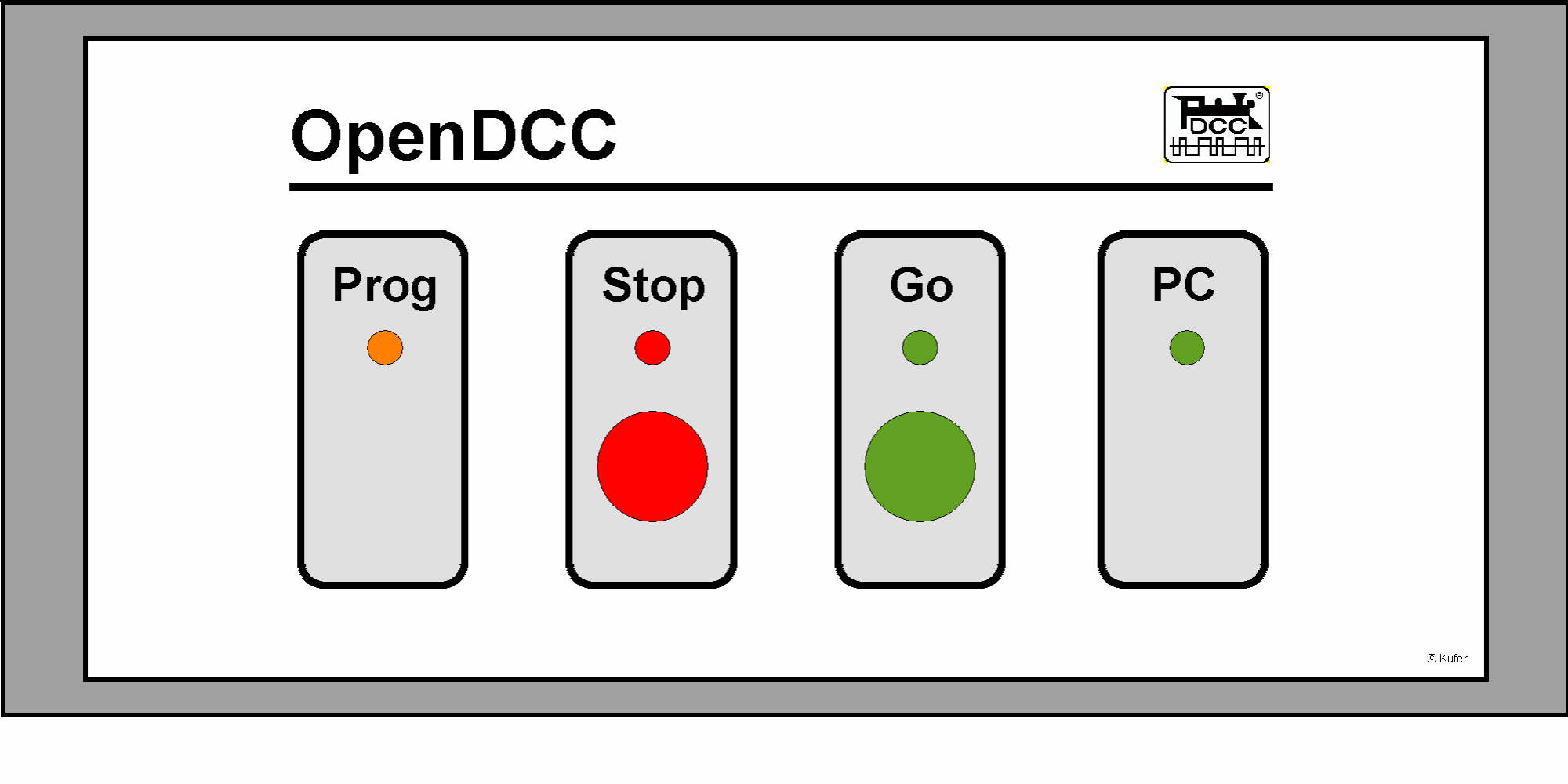
Front (Fischer cabinet):
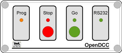
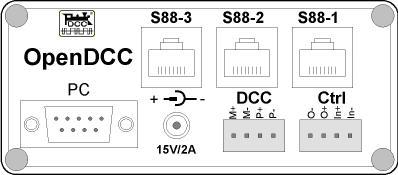
Back:
Front (Teko Cab 022):
Back:
Dimensional sketch Front (Teko Cab 022):

Dimensional sketch Back (Teko Cab 022):
Documentation
- Frontplattenentwurf_Teko_V1.1.dsf (MicroGraphx Designer) (for V1.1 up to 1.3)
Frontplattenentwurf_Teko_V1.4.dsf (MicroGraphx Designer) (for V1.4, new labeling S88-N)
Frontplattenentwurf_Teko_V1.4XP.dsf (MicroGraphx Designer) (for V1.4, new labeling S88-N, Xpressnet plug)
opendcc_front14.pdf (version V1.4, updated S88-N labels, Xpressnet-plug)