OpenDCC - A Command Station for DCC - Construction manual
Preface
-
According to VDE, the German Association for Electrical, Electronic and Information Technologies,
a model railroad belongs to toys which means there are strong protective regulations.
Norbert Martsch contributed a link to a prepared shopping card at reichelt.de, a German vendor for electronic parts.
Hints for soldering
- First of all the usual stuff: use electronical soldering iron (not above 300W;-),
appropriate solder wire (no Tiffany lead solder),
Diodes and Capacitors require correct polarity (small bar or '+' within the layout),
ICs are electrostatically at risk, in short words: beginners shouldn't start with this circuitry as a first exercise.
On the other hand there are no real challenges except the USB Chip in Surface-mount technology. The values of Resistors and Capacitors are usually not critical, within the circuit diagram there are hints for the electrical parameters (exceptions: R37 (only used for PTH switching regulator) must have 1%: 348 Ohm, R32 and R10 must be Metal-film resistors). LED's polarity is visible by long lead for anode (A, +) and a short lead for cathode (K, -).
IC1 (H-bridge) shouldn't be mounted on a socket to enable straight heat dissipation to the board.
The USB Chip FT232RL is supplied in a 28 pin SSOP package on a 0,65 mm pitch. Start to solder the corner pad on the board, then place the chip onto it, align all pins and pads while heating and soldering the corner pin. After this continue to solder the rest of the pins onto the pads. Use a fine soldering tip supported by a helpful 0.5mm solder tin wire ;-). Don't panic should two pins get connected! Don't frizzle too long but let it cool down and collect the spare tin with desoldering braid. Check all soldered joints afterwards with a loupe.
Mounting the Crystal oscillator may result in a short through the metal package and the SMD pads on the board. Either use a tape or just keep some space from the board.
Preparation
-
Before assembling the electric components you need to cut the Euro-sized board along the pink lines
into five board parts:
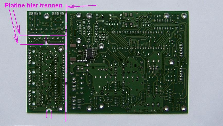
-
Base board: 120mm * 100mm
S88 board: 70*38 mm
Push button board: 38 * 23mm
2 tiny LED boards: 17 * 5mm
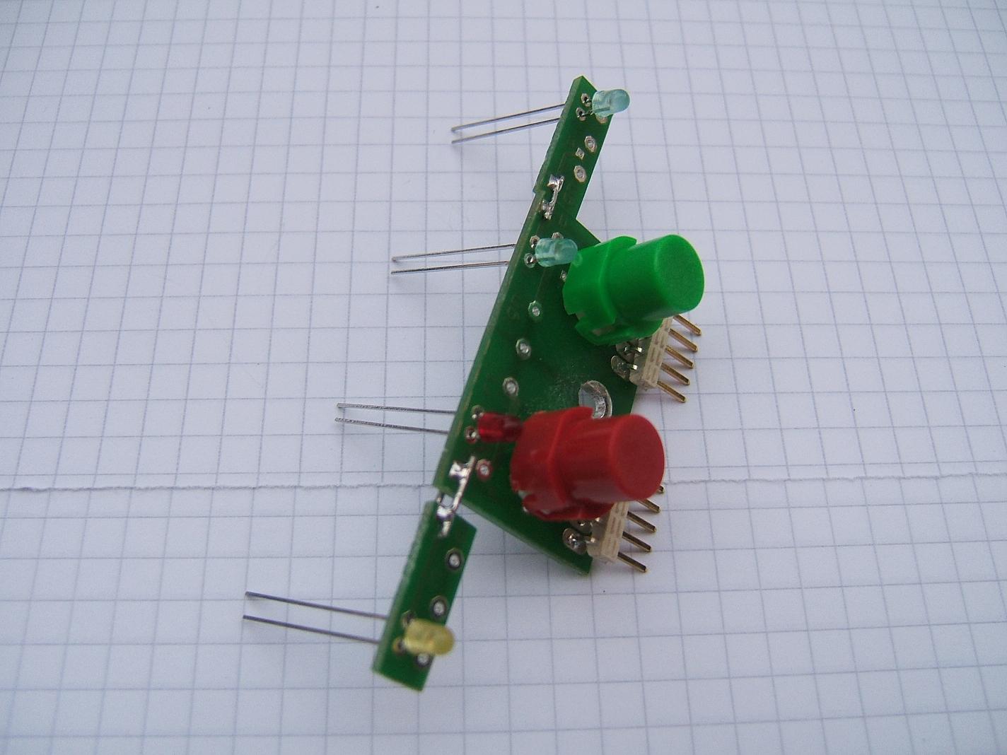
The Push button board together with the 2 tiny LED boards is built into a Front board like this:
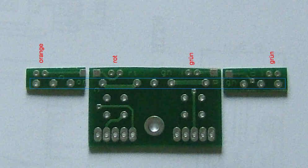
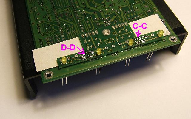
Connect all 3 parts by soldering small wire bridges (e. g. taken from cuts of resistor legs) onto the pads according to the letters A-A to D-D. This results in identical spacing between the LEDs. The front board will be mounted vertically onto the base board. A-A and B-B will be in the rear, C-C and D-D in the front. Use the main pcb or a scratch pcb as mounting guide. Keep it alongside the (virtual) blue lines, optionally you may add a bracing if needed at all.
Base Board
 |
 |
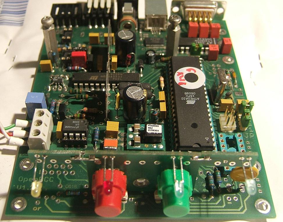
| Firstly you should solder the tiny surface mounted devices (SMDs) around the USB connector. | Secondly continue with resistors, diodes, sockets. See the board component placement diagrams for placement of resisters, capacitors, and other components. |
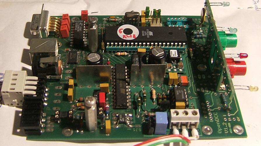
Then mount ICs, capacitors, connectors. The rear connectors should be aligned to the rear panel of the box. For the RS232 driver there are 2 options: Max232 or LT1080. If you go for Max232, keep an eye on the right position of pin 1 which is shifted by 1 (you'll recognize the start pads on the board).
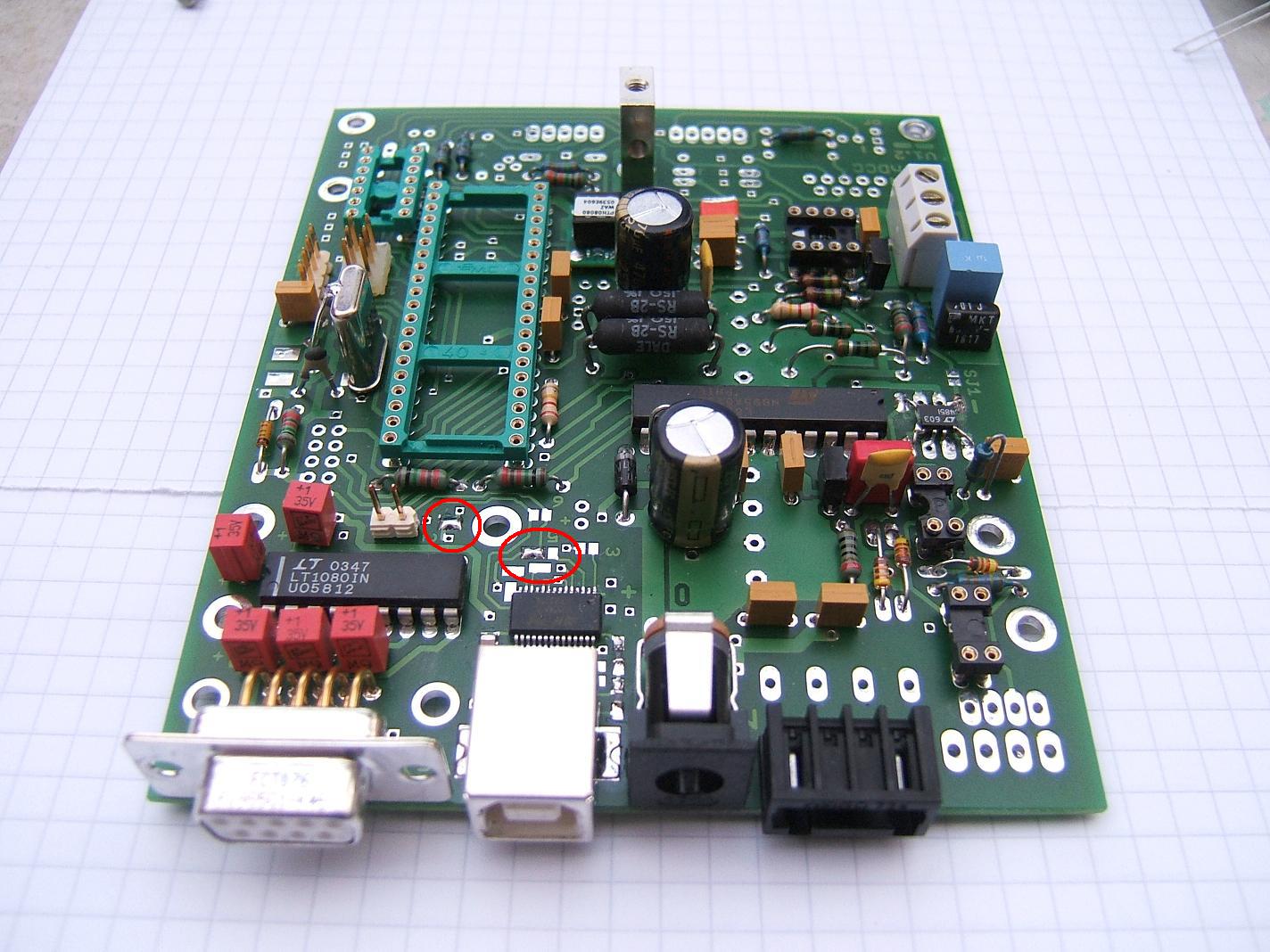
Above the completely mounted board, view from behind. Hint: in this case both PC interfaces are added, usually one was sufficient. The used interface needs to be selected by jumpers JP5 and JP6. It's 3 contacts, middle-left or middle-right need to be selected accordingly (the red circles mark the positions on version 1.3 boards, in this case RS232 is selected by solder jumpers, version 1.4 uses plug jumpers).
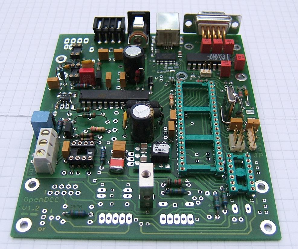
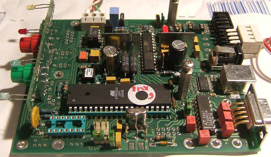
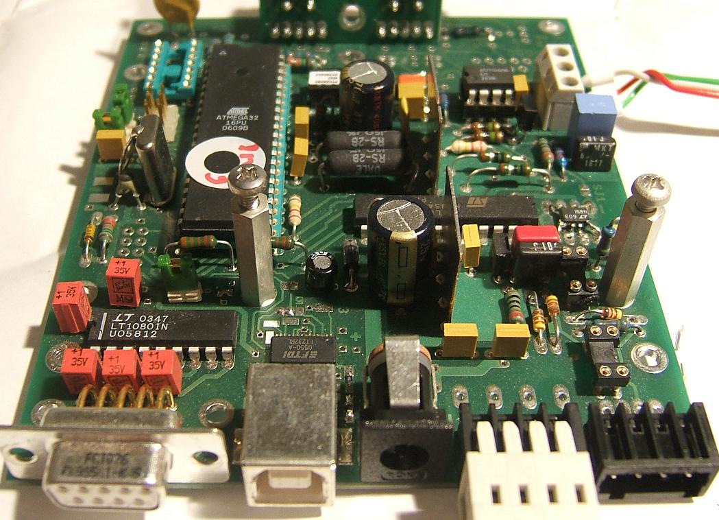
Above the completely mounted board, front view (missing parts are only needed for ponyprog interface).
Front Board (push buttons, LEDs)
-
Firstly assemble the front board from the push button and the 2 tiny LED boards as described above.
[*** müssen wir eigentlich nicht nochmal beschreiben, oder? ***]
This results in a LED distance of a 22.86mm grid. If you had another empty grid board available you can
use this to align it or use a multi-pin connector to align and as bracing to stabilize.
(picture)
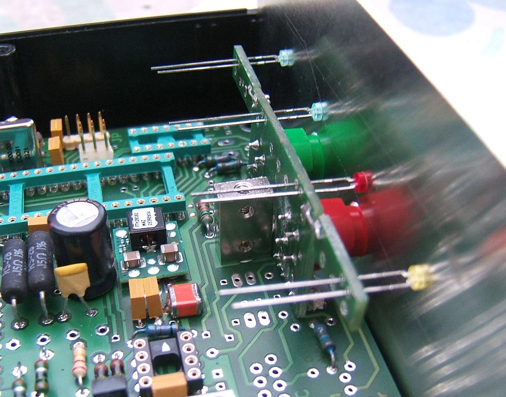
This front board will be mounted on the base board vertically in the middle. Use two 5-pin angled connectors (or left cuts of resistor legs). Connect, but don't solder yet.
Now solder the push buttons onto the front board, all other parts still will be left unsoldered in order to be able to align it. Screw the front board on the base board by using a cube of threads (e. g. available at German Bürklin, part number 17H912). Once the push button board is aligned to the front panel you may solder the two 5-pin angled connectors.
Hint by Alex: instead of a cube of threads you also may use any thick metal wires inserted diagonal. And, he found out a similar cube of threads with part number "GB4xM3" is available at http://www.qrpshop.de/
 |
 |
 |
 |
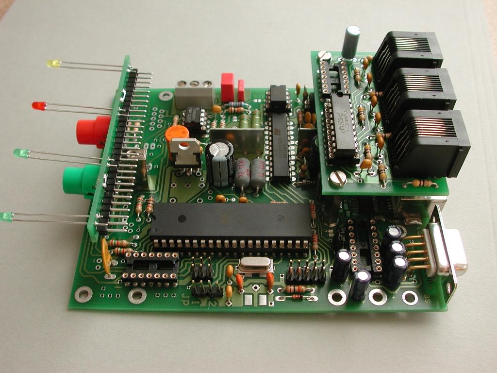
| Front board, LEDs still loosely coupled in their hole. | After having checked the positioning in the box move the LEDs into the front panel holes and solder it. | The boards assemble like this. | This is like the mounting fits into the box. |
Complete board
 |
 |
 |
 |
| Front view | Right hand view | Left hand view | Rear view |
Rear panel
-
The rear panel offers the PC RS232 plug, power entry, USB plug, DCC out plug and Ctrl In-Out plug
which all have been mounted onto the base board.
You should use the drilled and cut rear panel for proper alignement.
The S88 interface board will be mounted as a piggy-back board by using a 20 mm bolt for M3 screws.
It will be connected to the base board via a 14-pin connector cable with cutting clamp plugs.
From board version 1.4 protocol S88 is wired according to S88-n . This enables RAILDATA transfer. Only in this case resistors R41, R43, R44, R45 need to be mounted. Otherwise for normal usage these are not needed, but solder jumper SJ2 (found on the bottom side of S88 board) needs to be closed.
Attention:
There are different plug types available: Either plug pin 1 maps to cable lead 1, or alternatively plug pin 14 maps to cable lead 1. No matter what type is used as long it is used on both sides identical way. Should a 14 pin plug not be available you also may use a 16 pin plug - that's why there are additional vacancies in the pcb.
Hint for compacting the plugs: Build a hub of 3 breadboards e. g. by soldering together and use it as a base to press it through a bench vice.
Case
-
The board including all piggy-back boards may be slid into the Fischer
case respectively mounted by screws onto the Teko case sockets.
The front and rear panels are drilled and cut according to these layout drafts.
Should you want to use the board as DMX interface as well (not longer recommended), you need to connect the XLR-plug via an according cable to the 3-pin screw clamp. The connection number will be identical to XLR pin number.
Hint: should you plan to install a light steering it is recommended rather to use the decoder. In future software versions the DMX support may vanish.
First switching-on test
-
After having mounted all parts, do a visual check and wash away possible rests of flux by using some alcohol.
So far do not yet plug or mount the Atmel processor!
Now connect voltage for the first time, use a laboratory power supply unit - limit current to 50 mA.
Check 5V at voltage regulator, then test LEDs: Connect a 220 Ohm resistor to ground and on the other side to Atmel socket pins 28, 29, 35, 36 - check if LEDs are glowing. Now start mounting left parts.
When everything is mounted, connect voltage again: standby current should be around 30 mA having not yet programmed Atmel. Having Atmel programmed it increases to around 50 mA. Standby current increases again using the 5V voltage regulator and DCC-out is equipped with a RC low pass filter (+60 mA).
Initial programming of processor
-
After having completed hardware, the processor needs configuration and firmware loading. This is done through 3 steps:
- Set Fuses
- Import Boot loader
- Update Firmware
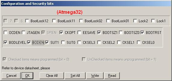
Atmel ATmega32 provides multiple pulse modes and boot load modes, which are configured by fuses. OpenDCC processor's fuse bits are set like this:
| Fuse bits | ||
|---|---|---|
| CKSEL3...0 | = 1111 | all flags unprogrammed (unchecked): means (16MHz) External Crystal clocking used |
| CKOPT | = 0 | flag programmed (checked): the Oscillator output will oscillate will a full railto-rail swing on the output, the output from XTAL2 drives a second clock buffer |
| SUT1..0 | = 0 1 | flag SUT1 programmed, SUT0 unprogrammed (Power Up Delay) |
| BOOTSZ1..0 | = 0 1 | flag BOOTSZ1 programmed, BOOTSZ0 unprogrammed; Start at 0x7800 |
| BOOTRST | = 0 | flag programmed, means Bootloader is used. -> see FW Update |
| BODLEVEL | = 0 | flag programmed, means Brown-Out Detector trigger level at 4V. |
| BODEN | = 0 | flag programmed, means Brown-Out enabled. |
If using PonyPorg/ISP the jumper JP4 needs to be disconnected, because otherwise it will conflict with RS232. Following the initial programming with ponyprog is described.
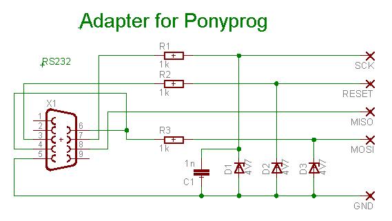 This is an adapter description for ISP-interface, which also may be built up separately (perhaps you want to reuse it in
other projects).
This is an adapter description for ISP-interface, which also may be built up separately (perhaps you want to reuse it in
other projects).
Attention: For this adapter within the Ponyprog Configuration you need the check "Invert Reset".
If not using the PonyProg on the board you need to connected the adapter to the 6-pin ISP-interface and import the bootloader; afterwards it can be unplugged (by the way, it may be used to program other project processors as well).
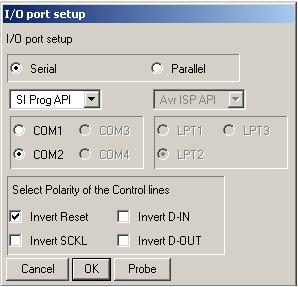
First of all check the correct ponyprog I/O setup settings. For OpenDCC you need the check "Invert Reset".
This is how the fusebits are written (for activated bootloader). I recommend to follow the sequence: Read - Change - Program (Write).
For loading the bootloader the file bootloader.hex needs to be opened and then sent to the Atmega using command write program. There is no EEPROM-File necessary for the Bootloader.
Attention: If the bootloader is not wanted, uncheck BOOTRST flag. The application and EEPROM needs to be loaded via ponyprog as well in this case (be aware there is no way to update via USB/RS232 then...)
Fuses for Atmega644P (for Xpressnet)
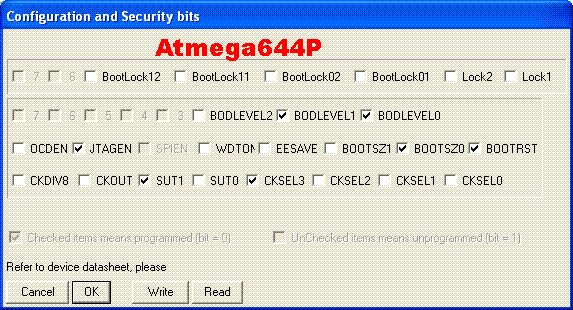
Please keep in mind, the official ponyprog version does not support Atmega644P, refer to FAQs.
| Fuses for ATmega644P | Value | Result | |||||||
|---|---|---|---|---|---|---|---|---|---|
| Lock Bit Byte | |||||||||
| 7 | 6 | 5 | 4 | 3 | 2 | 1 | 0 | ||
| 1 | 1 | 1 | 1 | 1 | 1 | 1 | 1 | 0xFF | not locked |
| Extended Fuse Byte | |||||||||
| 7 | 6 | 5 | 4 | 3 | 2 | 1 | 0 | ||
| - | - | - | - | - | BOD2 | BOD1 | BOD0 | ||
| 1 | 1 | 1 | 1 | 1 | 1 | 0 | 0 | 0xFC | 100 = 4.3V |
| Fuse High Byte | |||||||||
| 7 | 6 | 5 | 4 | 3 | 2 | 1 | 0 | ||
| OCDEN | JTAGEN | SPIEN | WDTON | EESAVE | BOOTSZ1 | BOOTSZ0 | BOOTRST | ||
| 1 | 0 | 0 | 1 | 1 | 1 | 0 | 0 | 0x9C | enter boot @0x7C00 (words) |
| Fuse Low Byte | |||||||||
| 7 | 6 | 5 | 4 | 3 | 2 | 1 | 0 | ||
| CKDIV8 | CKOUT | SUT1 | SUT0 | CKSEL3 | CKSEL2 | CKSEL1 | CKSEL0 | ||
| 1 | 1 | 0 | 1 | 0 | 1 | 1 | 1 | 0xD7 | no div, crystal, BOD enabled |
USB programming
-
Before using USB chip it needs to be initially configured
(this step is only required when using the USB-interface at all).
OpenDCC application loading
-
Now the application needs to be loaded, which is basically the same procedure as regular
Software Update:
- Push STOP button while starting.
- Yellow LED is glowing and the bootloader within OpenDCC is waiting on Download of program and EEPROM memory contents.
- Attention: Make sure to have configured USB chip before, otherwise there is no PC-OpenDCC connection possible for the update.
OpenDCC configuration
-
In a final step personal settings may be applied (optional).
These are stored at the internal configuration variables.
There are several ways to read or write these, some convenient are Rocrail, or Trainprogrammer.
What to do if it's not working?
-
First of all, don't panic :-)
- Check all parts if at the right place and correct polarity orientation.
- Check all plug jumpers (JP) and solder jumpers (SJ).
- Check all solderings and pcb (printed circuit board) tracks - if possible with a optician's loupe or magnifier.
- Check of voltage regulator value 5V and standby current 30-50 mA.
- Check if Atmel's signature is readable: Atmega644P: 1E 96 0A
- Check if programming is possible - if yes, can you read it back with Ponyprog?
- Check of Atmel's reset and frequency oscillator: XTAL2 (Atmel's output from the inverting oscillator amplifier) is 16MHz.
(Rest must be high, 16MHz is measured with a scope) - If firmware update is not possible via USB/RS232 after bootloader configuration, try to load firmware directly via ISP/Ponyprog and activate test mode. Are both .hex and .eep loaded?
- Jumper 4 correctly set? For Ponyprog programming remove connector. Connect for regular usage.
- Hint by Jan: While first testing the Processor with Crystal did not start, because there was a short cut of SMD pads by Crystal metal jacket. Please use isolator, adhesive tape or keep clearance.
- Switch on Test mode: Set both Jumpers (JP1 and JP2), there is a running-light of all 4 LEDs; within Test mode OpenDCC simply sends back the received Byte (with 19200 Baud) - you may check this with any Terminal application (i.e. realterm). This Test mode also works for USB!
- Check if RS232 chip creates +/- 8-10V. I experienced a capacitor defect at a brand new capacitor.
- Check if the used serial cable covers all the handshake lines.
- Should the buttons not work: check if not wrongly assembled rotated by 90°?
Then check the following:
Links
- Build report including additional hints by Stefan Linz (in German)
Build report by Guus Weggemans (in Dutch)
Farnell vendor for private customers: Fa. Heinz Büchner Elektronik, Berlin, Germany