Xpressnet™
Introduction
-
Xpressnet™ is a bus system for model railways to interconnect input devices,
computer interfaces and stationary decoder or feedback detectors.
Many commercial input devices (including the multi-mouse from Roco)
are based on this bus. OpenDCC Z1
is able to act as Xpressnet bus master.
Transmission technique
-
Transmission takes place at RS485
half duplex, which is a differential transmission technique on two lines;
these lines are terminated at both ends with 120 ohms. Typically one termination resistor is inside
the command station.
- each client detect an open bus as 1 (fail-safe). Level 1 equals IDLE on a normal serial line.
- when no node drives the bus, it should show a logical 1. This is achieved with a pull-up resistor on A and pull-down resistor in line B. (Biasing).
Source nodes must generate at least 1,5V, the receiver must be able to detect a signal with more than 200mV.
Linear and star-shaped topologies are possible, network and ring structures are not allowed. The maximum expansion is given as 1000m, but then it should be a linear structure and a termination should be added at the most distant nodes. Anyway, stubs cause reflexions (esp. long stubs), so it is a good idea keep the wiring linear shaped.
The transmitters are short-circuit proof for short duration, so that brief synchronous (transmit at the same time) transmission of two broadcasting stations does not lead to defects. Also, devices can be plugged and unplugged during operation.
Transmittion takes place with 9 bits, no parity and one stop bit, with a baud rate setting of 62500 baud. RS485 could do more (up to 10Mbps over short distances), but the speed is reduced to 62.5 kBaud for easier processing in the terminals and freedom in the network topology (branch lines).
Data reception is normally done with uarts, a permission token is assigned accoring the arbitration technique shown below. The bus will go in idle state during handover between master and clients. To avoid false triggering of the uarts in this phase, is is required that:
For electrical reasons, up to 32 devices can be connected. Each participant creates a load on the bus (known as unit load, a hypothetical load size). This number of participants is also reflected in the protocol level (see below). However, now many bus transceivers with lower level of bus loads are available, so that now even more participants are electrically possible.
Physical implementation, plug
- There are two different connector types:
- DIN circular connector
Xpressnet, DIN Plug 
Pin Farbe Name Description 1 yellow L Power, +12V 2 - - offen 3 black M Masse, GND 4 green A RS485 + 5 red B RS485 - - Modular Plug
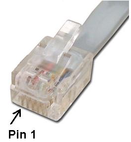
This connector is the connector in use today. It is RJ12 / RJ11 (to be more precise: RJ25) all 6 pins are used, the pinning is in accordance with the following table.
The track signal C and D is optional and serves as the supply of decoders or boosters. Standard 4-wire or 6-wire phone cable is used. Whenever possible, the lines A and B should be twisted.Xpressnet, RJ12 Plug 
Pin Farbe Name Description 1 white C track signal, DCC (optional) 2 black M GND 3 red B RS485 - 4 green A RS485 + 5 yellow L Power, +12V 6 blau D track signal, DCC (optional)
Bus Arbitration
-
The timing on the bus is set by the command station.
The command station sends either tokens or messages and then switches of its transceiver
for a certain period. Any transfer from the command station
will start with a specific byte, known as callbyte.
This callbyte contains the addressee of the message
(= client, value of 1..31) and 2 bits, which indicates the type of message.
Callbytes always have the bit 8 (the MSB) set, so the clients can recognize the beginning of messages (framing).
If the client address is 0, the message is addressed to all clients (broadcast).
To handover the bus to a client, the command station sends a token in any random sequence to the clients. The token is a callbyte, it includes the client's address (1 .31), 0x40, and the bit 8 (i.e. the MSB) set to 1. After receiving a token, the targeted client may answer within a time window of 80 µs. it is allowed to send one (and only one) answer message, which may case by case cause a reply from the command station.
The transmitted messages are grouped together in packages, these consist of:
| Xpressnet Messages | ||
|---|---|---|
| 1 Byte | 1 - 15 Bytes | 1 Byte |
| header ID and length of message |
payload i.e. loco address and speed |
checksum XOR, covering header and payload |
Problems and shortcomings
- Limited number of bus users.
Xpressnet can address 31 bus subscribers (clients) even if more is possible nowadays with RS485, it is still limited by the protocol level to 31. And this can however get together quickly: a few control devices, PC interface, feedback, Railcom - detectors ...
In Xpressnet there are no specs for the bustransceivers and only some vague notes on possible routing topology. Therefore no data is available up to what extend the bus is working stable. When analysing some commercial xpressnet devices one will find transceivers suitable for point-to-point connections, not for multi-drop networks. - Address space for accessory decoders and feedback
Xpressnet can address only 1024 different accessory decoder, this is a significant limitation compared to the DCC standard, where 2040 addresses are available. To make things worse, this address space is occupied in the lower half by feedback sensors, sharing the same space (no distinction is made in the protocol). In addition, the bit assignment of the query commands is a bit "unlucky", so you can really only follow the recommendation of Lenz and map the turnout up to address 64, then start with the mapping of feedback devices. Consequence: only 256 points are meaningfully accessible. - Advanced Accessory Decoder
For signal decoder and also for turnouts with multiple positions, DCC provides a special command, which codes the aspect directly. Xpressnet (with original command set) cannot handle these types of commands. - Programming for accessory decoders
Xpressnet cannot program accessory decoders by PoM - astonishingly for a company which claims DCC technological leadership. - Query and reservation of locomotives
It is possible to query the properties of a locomotive (ie actual speed and max. speed steps, lights, and functions) from the command station. However, the answer is always related to the previous request, the locomotive address itself is not included. If you try to query more than one loco from one client, you have to mutex the queries. This is very inconvinient for a base station for several remote control units.
On Xpressnet locomotives can not be reserved for a particular throttle, locomotive objects can be 'stolen' from every other handheld. This is certainly not a problem at small layouts at home, but on a larger club layout you would like a protection.
Links
-
www.lenzusa.com/manuals/xpressnet/xpressnet.pdf
command summary; Erweiterung für fast clock, für BiDi and feedback
Xpressnet plugs
Extension of OpenDCC Z1 for Xpressnet
Sniffer for Xpressnet
Railcom Xpressnet Translator
Xpressnet - Ethernet Bridge (inkl. TCP/IP to serial converter)