DCC Data Transmission, Considerations on Bit Errors
-
Revision:
0.01 2021-04-22 kw start
Content
-
1. Introduction
2. Error sources
3. Receiving technologies
4. Usage of check codes
5. Practical experiments / measurements
7. Official Tests
7. Summary
1. Introduction
- In the discussion about standardization of new commands, such as RCN128, DCC-A
a consideration of the necessary error protection is needed.
For this, however, a prior consideration of the possible errors and their
detectability by the receiving technology is important. Due to the limited resource bandwidth,
the code effort for error protection should be kept minimal, but at the same time be sufficient.
Since model railroading is not a technology where a malfunction has extreme effects (e.g., compared to a control system for power plants), the target is certainly not 10-18, but you will be satisfied with much smaller dimensions.
This page contains a summary of common error sources and their possible modeling, there are considerations how different receiving technologies affect the error detection and what should be done in the command code for protection.
The situation is complicated by the fact that the individual bits have a variable length, so error sources affect 0 and 1 differently, error-correcting procedures can hardly handle this: the length of a 0 is approximately the length of two 1 bits.
2. Error sources
- If you look at the sources of errors on model railroads, you are not dealing with normal,
noise-like statistical influences, but the errors are often systematic and not accessible to classical error analysis.
- Power interruptions
This is usually caused by problems in the wheel-rail contact or by switching operations (e.g., in a reversing loop). Power interruptions lead with noticeably short durations to extension of the current bit phase (voltage level simply remains), with longer interruptions to a drop of the voltage at the decoder and to an abort/restart of the DCC receiving.
The duration of power interruptions is difficult to estimate, but two possible sources may be considered here:- Contact wheel to rail:
Suppose a wheel runs over a hair on the track. The wheel will take off and touch down again after the hair. How long does this process take?
Here is a simple example calculation: Assumptions: The model runs 0.3m/s (=100km/h, 1:87). Wheel diameter 11mm (wheel circumference: 34.6mm), a hair with 0.1mm diameter on the rail.
The angular velocity of the wheel is given by: 300mm/34.6mm = 8.7 rounds per second; scaled by 360° gives 3120°/s.
The wheel lifts off when cos(phi) = 5.4/5.5. This calculates phi = arccos(5.4/5.5) = 11°; i.e. the wheel is in the air for 22°.
With the angular velocity above, this results in a drop of 7.05ms.
Of course, not only one wheel is involved in the current transfer, but the possible interruptions may well extend into the milliseconds range. - Switching operations:
Common relays have switching times from about 400us to about 1ms. (These values come from a test series on a reversing loop module)
- Contact wheel to rail:
- Short circuits
Wheel angles in the range of 5° to 15° are likely to be involved. Analogous to the above consideration, this results in drops in the range of 1ms to 3ms. - Systematic errors, correlated
These can be caused, for example, by unclean booster edges. However, systematic errors are likely to lead to such a high bit error rate that operation is hardly possible, and an error analysis is unnecessary. - Systematic errors, not correlated This can be, for example, interference from other decoders whose motor drivers causes the level on the track to collapse. The result is noticeably short (in the range of a few µs) voltage drops on the track.
3. Receiving technologies
- The reception technology has a significant influence on the primary error probability.
This can be roughly divided into the following technologies:
- Edge triggering:
An edge (as interrupt) is used to make the bit decision together with a timer. This method is extremely susceptible to interference and can only be used with stationary decoders. - Edge analysis:
One edge is (or both edges are) measured and the bit decision is made from this. The procedure sorts out the above errors very well because the errors either lengthen or shorten a bit inadmissibly. If both edges are evaluated, the 'skewed' return of the algorithm to a correct sequence of half bits is also detected. - Sampling:
The signal is sampled, depending on the resolution of the sampler, interferences are detected and a DCC message is discarded. If the sampler operates in quite rough raster, it becomes increasingly more susceptible to interference. Also, with sampling there is then still the difference of the single or double edge evaluation. In the border case of exceptionally fine scanning resolution the scanning is identical to the edge evaluation.
A close detection of the timing helps to detect the above errors reliably.
If you also exclude the possibility of using longer 0-bits during reception
(so-called zero-stretching to support an analog locomotive running in parallel),
you get an additional, good protection against the longer signal
interruptions due to contact loss or short circuit.
4. Usage of Check Codes
Initial situation
Various techniques are known for safeguarding (XOR, addition method, CRC with different polynomials, FEC). Radio technology in particular, has produced many methods because of frequent bit errors during transmission. However, all known investigations usually focus on messages that are much longer than what is available here at DCC.In the case of very short messages, XOR and CRC are equivalent; the advantages of CRC (continuous spread of collected bit errors over the entire checksum word) do not yet come into play. In addition, statically evenly distributed errors are usually assumed, which only partially apply here.
With DCC, there is the (historically determined) specification of the XOR at the end of a message. For reasons of compatibility with existing boosters and decoders, it is also recommended to be maintained for any new messages. At most, a combination of CRC + XOR or a general CRC for certain initial bytes would be conceivable.
Theoretical consideration
-
Checksum codes are used to detect bit errors and to purge wrong message. Key parameter of a code is the
capability of avoiding false-positives (not detecting an error). Every code does this for single bit errors, but when it
comes to multiple errors, we see differences.
- XOR generates a false-positive if two bits flip in the same data word. I.e. considering a 6 byte message, we have a length of
48 bits. The error probability for a single bit error is p. Then we can calculate the probability for a double error as:
(1-p)46 * p2 * (48 over 2)
with (48 over 2) evaluates to 48 * 47 / 2 = 1128. This would be value for a single XOR bit. However, DCC does a bytewise XOR. Here this false-positive is only possible, if the same bit position in the byte is affected. This reduces the number of possible partners for a double error from 47 to 5. The probability for a false-positive reduces by a factor of 5/47.
How does this scale with data word length: (1-p)^length can be evaluated for small values of p into a series, the first term being linear: p*length. For small values of p this can be neglected, too and we see p^2 * (length over 2) as dominant component. For XOR, In general the probability for undetected double error raises with the square of the data word length, on bytewide XOR this is scaled with (B/8-1)/(B-1) (B=total data word length). - Im comparision a (theoretically assumed perfect) CRC. Such a CRC spreads the bit error statistically equal to all checksum bits. The chance for two identical spreads is 1/(2^crc_length), on a 8 bit CRC this is 1/256. Instead of a gain 5/47 we get 1/256. (However: this is only valid if the spread is possible between the bit errors, i.e. there are sufficiant shift + divide operations between the errors. This is not always true.)
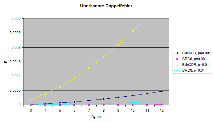
Shown: for different bit error probabilities p the value for undetected double errors (false-positive). For larger single bits error values the XOR method gets more an more prone for this undetected double errors. For longer data word length CRC is clearly the better choice.
Implementation
- When implementing a certain check sum technique, available computing power and timing requirements must also be considered:
- XOR is available on all systems. In model railway decoders often 8 bit processors are used, typically such
processors do not offer a a hardware unit for CRC.
Newer generations like ARM Cortex M3, M33 do have hardware support for some 16- or 32-bit polynoms.
CRC can be calculated bitwise or wordwise (based on tables). It can be implemented very fast with a single xor operation and a table lookup, however this requires a table of length 2n in memory. - Calculation timing can be critical, since the decoder need to check the correct reception of the DCC message before it can send out the railcom answer. The time gap between end of DCC message and start of railcom message is very small, thus a possible railcom answer is typically precalculated and enabled only in case of checksum=good. Therefore checksum calculation must be performed inside the receiving interrupt routines.
Literature
-
The Effectiveness of Checksums for Embedded Networks:
This work compares XOR, CRC and some other methods, evaluates bit- and burst errors,
however the focus is on longer sequences than relevant for DCC. A conclusion of this work is the acceptable performance
of XOR when considering burst errors, but in systems with single bit errors XOR looses significantly against CRC.
Cyclic Redundancy Code (CRC) Polynomial Selection For Embedded Networks This work covers selection criteria and proposals for 'known good' CRC polynomals, especially considering short data word length.
Internet Protocol Small Computer System Interface (iSCSI) Cyclic Redundancy Check (CRC)/Checksum Considerations, RFC3385;
This work covers pud (probability of undiscovered double errors) on CRC, however the main focus is on very small error rates (less than 10-10.
5. Practical experiments / measurements
- When Railcom-QoS was introduced, "Döhler und Haass"
carried out series of measurements to check the functionality of QoS.
The error detection were checked in real operation (test system) with various models,
gauges and degrees of track pollution.
- Error source 1: Most of the errors were so-called "clock pause errors".
(Explanation: D&H also supports SX; with SX, the bits on the track are separated by a so-called "clock pause" (= short "cutout" with a length of 10µs). This must not be longer than 15µs, otherwise reception is aborted; there must be a clock pause for SX between each bit.
Such a check is "unnecessary" for DCC, but common code for data acquisition, DCC is also analyzed with the accuracy required for SX. ) - Error source 2: timing errors … in the first half of the DCC signal. Neither a "1" (around 58µs) nor a "0" (from 100µs) being recognized.
- Error source 3: "mismatch" errors … meaning the first half of the bit was recognized as "half 1", the second half was recognized as "half 0" (or vice versa). Not a single package "got around" these three sources of error.
- 1. DCC evaluation with edge evaluation on both sides, XOR check activated. (Regular operation of the decoder)
- 2. DCC evaluation with edge evaluation on both sides, XOR check deactivated.
- 3. DCC evaluation with one-sided edge evaluation, XOR check activated.
- 4. DCC evaluation with one-sided edge evaluation, XOR check deactivated. The tests were carried out with routes with various levels of dirt (which resulted in a reception quality (QoS) of 5% to 100%).
- Case 1. (both edges + XOR): Down to a reception quality of 10%, a locomotive could still be controlled manually in an acceptable manner.
- Case 2. No difference to case 1. The DCC messages were already discarded before the XOR evaluation.
- Case 3. Below a reception quality of 25% there were sporadic malfunctions, messages were passed on to the evaluation despite XOR.
- Case 4. Hardly any reasonable operation possible.
Results:
More error source where defined: error source 4: invalid separator bit between the bytes, error source 5: invalid XOR checksum and error source 6: invalid packet length. However, these never occurred.
Based on these results, the detection reliability of errors was initially questioned (whether everything had been implemented correctly), since the sources of error four to six never occurred. A correspondingly manipulated DCC track signal generation could, however, prove that the decoder would also recognize these sources of error.
Test series at Tams Elektronik
There were investigations at the company Tams Elektronik for the same reason.
Here, too, a test locomotive was set up on a layout with different 'known bad' sections. The errors were checked by means of QoS and logging inside the decoder and also compared with the real driving impression. The test consisted of four arrangements:
Results:
6. Official tests
-
Unfortunately, there are no official test criteria yet, neither with the NMRA nor with the Railcommunity.
In the 1990s, the NMRA found problems with certain decoders on so-called 'bad layouts'. Measurements revealed non-monotonous edge transitions in the booster and superimposed coupling as root cause. For this the NMRA empirically embarrassed a test setup: the so-called 'glitch booster' is a booster with a particularly bad edge and the 'noise injector' which injects an unsubstantiated noise voltage onto the DCC signal. However, there is no documention available on the output of this test setup. But currently these signals are part of the conformity test.
These tests are not suitable to cover the real problems that could lead to bit errors. Investigations with this setup are therefore useless for a practical transfer test.
7. Summary
-
The main sources of interference with DCC do not lead to statistical bit errors but provoke timing errors.
These can be recognized well using suitable reception methods, which means that the
probability of errors is greatly reduced.
In comparison, CRC is clearly better than XOR for a downstream checksum,
but with small residual probabilities, XOR provides sufficiently good error detection.
Correct timing evaluation and observation of both edges / half bits when receiving is
therefore key to safe and functional operation. Correct timing evaluation will
significantly increase security even with short DCC commands.
A meaningful test of decoders that simulates real world issues such as contact problems at the wheel/rail transition could provide a well-founded statement about the need for timing evaluations and / or additional CRC.