Reverser for DCC
 |
 |
| Reverser V1.1 | Reverser V1.3 |
The new layout of my model club MEFM requires eight reversing modules, since the layout contains turn loop, track triangles and hidden turn loops. A discrete contruction was choosen, because it can better be integrated with feedback units. The reverser is installed after the feedback unit, this allows the feedback unit to supply other track segments as well.
Basic techniques for reversing
- A track loop or triangle contains in principle a place where wrong polarities of the track meet.
This is usually resolved by reversing (eg via relay or MOSFET) one section of the tracks.
Of course one must pay attention not to cause a short curcuit at another place of the layout.
- manual reverse of the section in question:
This is technically the simplest solution. However, it may sometimes be forgotten during operation and whow - a wonderful short-circuit current is running through the vehicle. In a computer controlled layout manual reversing is unthinkable. - Coupled switching:
The reversing of tracks is coupled to the position of turnouts. This can used with simple turn loops and is sometimes advertised as "intelligent" switch. When running a more complex layout, there is often no conclusive rule for the right polarity. - Controlling the polarity from the planned schedule:
If the layout is operated automatically, then train is running on predefined schedules and the actual movement is normally monitored with some kind of detectors. In such an environment the reversion of a certain section can be done automatically. For examples, when using Train Controller, the appropriate switching points can be determined by virtual detectors and flagmen. Disadvantage: You always need a computer to operate the layout. - Controlling the polarity from the observed train movements:
More sophisticated is a solution which monitors (measures) the actual train movement and triggers the reverser. Advantage: this work in both manual mode and under computer control. Regarding the monitoring system, there are following solutions:- Acquisition by optical sensors: One pair of light barriers at both ends of the questionable section controls the relay. Disadvantage: The sensors require wiring and can't sometimes not been mounted (esp. in visible areas).
- Acquisition by current sensors:
a) One short disconnected section at both ends of the questionable section get powered 'backward' by the train. This current is detected and controls the relay. This is a circuit proposal for a such a reverser.
b) Acquisition with real current sensors as they are used in normal occupance detectors. The two sensor sections at each end (resp. their logic combining) will control the relay. - Acquisition with short curcuit sensors:
The detection is made by evaluation the short curcuit, which will happen if track with wrong polarity
are crossed. The current is measured and upon reaching a critical threshold,
the reversing takes place.
Advantage: none additional wiring is required.
Disadvantage: The reversing always takes places under load. This requries appropriate current rates of the relay and will create a short circuit of about 5ms. This may threaten an ongoing data transmission on the rails and will load a certain amount of energy in the point where the short happened. This may cause spots on the wheels. The energy can be reduced by a fast electronic shutdown of the supply, but not entirely eliminated.
The isolating position in the track never match exactly, moreover one is not sure which side of a locomotive will make the first contact to the other section, so the short circuit may happen either in the left or the right track. It is therefore necessary to monitor both leads. You will find a more detailed discussion of this topic at Blücher Elektronik, a provider of reversers.
- V1.1: simple circuit with short-circuit surveillance (one track)
- V1.2: additional input for computer control to avoid short-circuits in normal operation. This allows for smooth control in a computer driven layout as well as manually operation.
- V1.3: same curcuit as above, but surveillance of both sides and computer control input
It is a great advantage of DCC, that it is independant of track polarity. It is therefore possible to change the polarity of the track during the run - the locomotive will keep it's current direction. Of course, the actual message during this reversing with be corrupt, but this is recognized by the decoder and discarded without further consequences.
How can this reversing be triggered?
Properties
- Current: max. 5,0A, threshold or the reverser approx. 2A, selectable with resistor.
- Voltage: DC or DCC
- Supply: separate 12V supply with own transformer required
- Size: 80*50mm + AC adapter (V1.1, without a computer input)
- Size: 80*60mm + AC adapter (V1.2, with optocoupler input)
- Size: 80*80mm + AC adapter (V1.3, two side surveillance and with optocoupler input)
Installation and operation
- Power supply:
Connect AC or DC with 8-12V to X1-1 and X1-2. This supply may not simultaneously supply other circuits (eg Booster). In version 1.3, the reverser need a second power supply. This can be done either by X5-1 and X5-2 or alternatively by an integrated DC-DC converter. With dual external supply, these two voltage sources must be isolated, best is to use two plug power supplies.
DCC input:
Connect the DCC input from the booster to X2-1 and X2-2. Keep same polarity of neighboring track sections.
Track output:
The output (X3-1 and X3-2) is connected to the tracks, again keep the polarity.
Computer input (only in V1.2 and V1.3):
Connect the output of an accessory decoder to input (X4) (polarity does not matter). X4-2 = common connection, X4-1 = set reversing, X4-3 = Reset reversing.
Function:
When a train travels from a section of track with wrong polarity into the section controlled by the reverser, it will cause a short-circuit. The reverser recognizes this short (at approximately 2A) prior to the general turn off of the booster. The polarity on the track is reversed quickly, which usually fixes the short. Should the short circuit still exist despite reversion, so the normal short-circuit protection of the boosters turns off power.
After a trigger (and thus reversing) more shorts are ignored for about 1 sec to avoid multiple switching.
The revering section must Longer than the longest train, because otherwise short circuit could happen simultaneously at both ends.
In track triangles it may happen that no side is long enough for the reversing section. A possible solution is to fix on of the approaching track with an reverser.
Remote control:
From version 1.2 an interface for remote control from a computer was added. The two AC Optocouplers OK1 and OK2 activate either normal or reversed state. This can be achieved by a simple turnout command (eg, on a turnout decoder). The reverser will be in the right polarity before the train is crossing thus avoiding the micro shorts with computer operation.
Display:
orange LED (U1): Notification of active reversion
green LED (U2): Notification of adjacent supply voltage
Circuit Description
- Power supply:
The power input at X1 is rectified and used for the relay. IC4 generates the 5V supplies of the board.
Short-circuit surveillance:
The current of the track is fed through a shunt (0.05 ohms = two 0.1 ohm in parallel). A possible high frequency alternating current caused by wiring and track is dampened by C8. The voltage drop across this resistor (0.1 V at 2A) is compared with the comparators IC1A and IC1B to the voltage drop across the resistors R2 and R3 (390 ohms) = 0,1V. R5 (10k) and C6 (10n) define the response time (R * C = 100µs) of the short-circuit monitoring.
In version 1.3, this curcuit is contained doubled and thus both lines are monitored. The activation of a comparator causes a current through the opto coupler, thus triggering the mono flop.
Reversing:
If overcurrent is detected, one of the comparators is activated and triggers the following monostable filpflop IC2B (t = 1sec), the output of this monoflop triggers the flip-flop. The output of the flip-flop controls transistor Q1 and the relay K1 (type DS2). Thus the polarity of the track signal is reversed and the short is fixed.
The optocouplers (type SFH628AC) act on set and reset of the flip-flop, so that is possible to preset the reverser in the right position. The polarity of the signals applied to the OCs does not matter, since the LEDs in the optocouplers are bidirectional.
Construction Manual
- First, the usual remarks: suitable solder and solder iron, (not above 300W, no solder
for tiffany lamps ;-), semiconductors and C's mounted with correct polarisation
(there are small markers in layout, pin 1 or cathode), static CMOS ICs must be
handled properly ... in short who is doing his first steps in electronics,
this is not the circuit to start practicing.
The values of resistors, and C's are uncritical, instructions can be found in the schematic for different values. Initial powering should be done with a regulated lab power supply, limited to some mA current.
Changes from version 1.1 to 1.2:
23.05.05: supplement:     remote control-input with optocouplers added.
                          new layout, 80*60mm
Änderungen von Version 1.2 auf 1.3:
04.04.07: supplement:     surveillance on both lines.
                          new Layout, two-sided, 80*80mm
Problems and issues in versions 1.1 and 1.2:

During tests the reverser sometimes switched without reason.
If this occurs when a train is crossing the section short-circuit may happen.

The cause are high current peaks which may come from the simultaneous interaction
of following circumstances:
   a) change of polarity of the DCC signal
   b) burst of the PWM signal from the decoder to the motor
   c) Short-term interruption of contact between wheel and rail and therefore
      a reload of the caps in the decoder.

This leads to a crosstalk on the comparators which needs filtering.

Counter measures:
   1) 100 nF ceramic (SMD) in parallel with C10, 10uF
   2) remove C6 (10nF)
   3) add 2.2 nF (ceramic) between Pin 5 and pin 6 of IC1 (LM393);
      Mount as close as possible;
   4) add 2.2 nF (ceramic) between pin 2 and pin 3 of IC1 (LM393);
      Mount as close as possible;
   5) Value change: C9 from 10uF to 100uF; this increases the lockout time

A ferrit bead in the wiring to the track would improve the situation.
Documents, Links
- The following documents are provided for private use only.
Any further publication or commercial use is prohibited. There is no garantee,
liability for the accuracy or whatever. ;-)
Schematic and Layout (Version 1.1):
- Schematic (pdf), (eagle)
- Layout (pdf), (eagle)
Schematic and Layout (Version 1.2):
- Schematic (pdf), (eagle)
- Layout (pdf), (eagle)
Schematic and Layout (Version 1.3):
- Schematic (pdf), (eagle)
- Layout (pdf), (eagle)
Data sheets:
- LM393.pdf
- 74HCT123.pdf
Others:
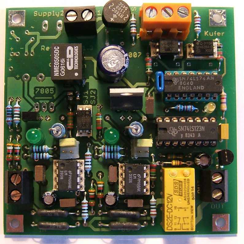
- picture of prototype
- reverser from amhamberg.de (with FET switch and Atmel AVR, but usable with feedback module, because it is supplied with track power.)