OpenDCC AniMat - Sequencer
- A wide application range (besides the direct control of each function) is opened by the sequencer software.
This allows to combine calls to individual function in a sequence. This sequence then may be triggered
by DCC, by an external input or by remote control.
How it works
- Imagine a cam axle, where you can put your own cams on it
(like in an mechanical musical-box).
You can give a cam not only a position (WHEN it gets activates)
but also an associated action (WHAT the cam activates).
"WHAT" could be any action like moving servo, turning output on/off, spinning motor, playing mp3.
And you can also position cams with properties like stop revolving, start other cam axle and wait for input.
The gap between cams is given with a variable which denotes a time value. Thus a complete cam definition always consists of two parts: time and target action.
AniMat can run up to eight such cam axles in parallel. These cam axles can be triggered by a DCC command, by an external input or direkty by USB.
These sequences makes the modelling of animated sceneries easier. I.E. a cable railway moving back and forth, or a railroad crossing, where first the lights are turned on, a warning sound is played and then the barriers are slowly lowered with a servos. And in parallel the stop magnet for Faller Car is activated.
See the applications section for more examples. There are numberous possible applications like merry-go-rounds, crane movements or other animated sceneries.
CV-Parameters for Sequencer mode
- For every DCC command there's a corresponding sequence and control parameter.
The control parameter defines the passing of time locally on the layout.
The sequence itself is comprised of up to 25 cams, whereby each cam
is made up of 2 data words (namely time and desired function).
The word length is one byte (CV).
As well as direct "action functions" there are also "administration functions", that allow sequences to be run one after another or to skip over each other etc. Therefore you can create longer sequences of more than 25 cams. Special cams also allow for the polling of contacts and switches.
Every sequence has a stored CV, which references the speed reduction (ratio) from real time:
CV [Base] + 0: SLOW_DOWN
With this CV the speed of the control unit is set. With a configuration of 1, the control unit processes instructions every 100ms. (default: 10 (=processing speed 1s))
In total then a control unit contains 51 CVs and there are 8 such control units in each decoder. The following table shows such a sequence. (Here only the particular offsets from start of this sequence are denoted).
| CV für one control unit | ||||
|---|---|---|---|---|
| CV 0 | SLOW DOWN | |||
| CV 1 | TIME | CV 2 | ACTION | Cam 1 |
| CV 3 | TIME | CV 4 | ACTION | Cam 2 |
| CV 5 | TIME | CV 6 | ACTION | Cam 3 |
| ... | TIME | ... | ACTION | Cam 4-24 |
| CV 49 | TIME | CV 50 | ACTION | Cam 25 |
Address(SLOW_DOWN) = [Base] + [control unit] * 51
Address(TIME) = [Base] + [control unit] * 51 - 1 + [cam] * 2
Address(ACTION) = [Base] + [control unit] * 51 + [cam] * 2
Cam Definition
- The individual actions in a sequence are defined by so called cams.
A cam is defined by a given time and a desired action
together with accompanying paramaters.
Unused cams are must be set to the value 0xFF 0xFF.
The cams are coded as follows:
| Time | 8 Bit | Input of a time as a number which references the preceeding
action in the sequence.
A time of 0 indicates that there should be no delay
between the actions
(thus there is a small delay, since they are physically carried out
immediately one after an other).
The time entered here refers to the number of ticks
until the next action takes place.
Only entries between 0 and 250 are valid.
The actual waiting time is derived by mulitiplying this time factor
by the speed of this control unit.
Therefore time periods from 100ms up to over 1.7 hours can be realised.
Time entries over 250 are reserved and are used for controlling the control unit. (see below) |
|---|---|---|
| Operation | 8 Bit | Here is a bit field for the different actions which we want to carry out. These actions are explained in the following table, together with their parameters. |
| Standard operations | |||||||||||||||
|---|---|---|---|---|---|---|---|---|---|---|---|---|---|---|---|
| Value (binary) | Action | Parameter | Notes | ||||||||||||
| 00aaaass | switch output |
|
The given output is switched to the desired status. With phase A, it starts in the "on phase", With phase B, it starts with the "off phase". | ||||||||||||
| 01mdssss | set motor |
|
The motor runs with the given settings at the desired rpm. The internal steps are finer than the given setting. | ||||||||||||
| 100srccc | move servo |
|
The servo carries out the given movement and positions itself at the given position. The servo is is moved in multi positions mode.. | ||||||||||||
| 101***** | reserved (probably for controlling stepper motors) | ||||||||||||||
| 110sssss | play sound |
|
Index 0 turns the sound off. | ||||||||||||
| 111***** | reserved | ||||||||||||||
When a time parameter of 255 is entered, a "system" operation is executed instead of a normal operation:
| System Operations | |||||
|---|---|---|---|---|---|
| Value (bin) | Action | Parameter | Notes | ||
| 0000pppp | query input for equal 0 |
|
If the selected input is equal 1, the sequence will be halted. If the selected input is equal 0, the sequence will be continued. | ||
| 0001pppp | query input for equal 1 |
|
If the selected input is equal 0, the sequence will be halted. If the selected input is equal 1, the sequence will be continued. | ||
| 00100sss | start sequence |
|
The given sequence is started, even the current sequence can also be re-started. Thus it will be repeated. This command will only be executed, when there's no sequence end trigger present. The current sequence is ended after the execution of this command. With this command sequences can be run one after another and therefore longer sequences can be created. The command must not appear at the beginning of a sequence. | ||
| 00110sss | stop sequence |
|
An 'end trigger message' is sent to the sequence to be stopped.
The receiving sequence stops executing any system commmands
(neither input polling nor other start commands). Normal control commands
continue to be carried out however.
If the sequence to be stopped is waiting for a system event
(eg input poll or message poll), then the sequence will also be stopped with this
end trigger. The called sequence is not ended. This command gives the ability to cancel infinitely looping sequences. | ||
| 01010sss | inhibit sequence start (*) |
|
The given sequence may not be started in parellel to the current sequence. This "lock" needs to be released afterwards. This command allows for preventing problematic combinations of sequences from running together. | ||
| 01011sss | enable sequence start (*) |
|
|||
| 01100nnn | clear message |
|
|||
| 01101nnn | set message |
|
|||
| 01110nnn | wait for message |
|
The sequence waits for the delivery of the specified message. This command serves to synchronise sequences. If a message is already present when this operation is called, the sequence will be continued immediately. If no message is present, the sequence pauses and waits the message. When a message eventually arrives, the sequence continues. The delivered message is not deleted. | ||
| 11111111 | end | - | This sequence is finished, nothing more should happen; That means, after a sequence end all unused cam entries must be set to 0xFF 0xFF. | ||
The cam control contains only the changes that are made over the run time of the sequence. At the beginning of a sequence, all outputs and internal states are in the same status as they were left in by the previous sequence which affected them (for example, a motor remains in the same position, it does not automatically return to "home" etc.). If you want to force a particular starting status, then a cam at time point 0 with the desired action should be entered.
Multiple cams may be associated with the same time (meaning that their time entries are then 0). These are then analysed and executed (nearly) simultaneously.
(*) = not implemented yet, depends on possible applications.
Programming Tool
- The definition of tabs and the creation of sequences is
hard work if you have to refer to the bit definitions all the time.
To make it a bit easier, here is a tool:
- Through a direct serial connection with the AniMat: To accomplish this a USB cable is connected to the expansion socket. This is the quickest way as the time consuming diversion through the slow DCC protocol is avoided. (Host-API commands are used)
- Through a DCC command station: p50x commands are used.
- Through TrainProgrammer (commercial software from www.freiwald.com): Using this method is independent of the DCC command station. (Note: Not yet running. At time of writing (Feb. 2010) the interface von TP to application programs is prone to errors)
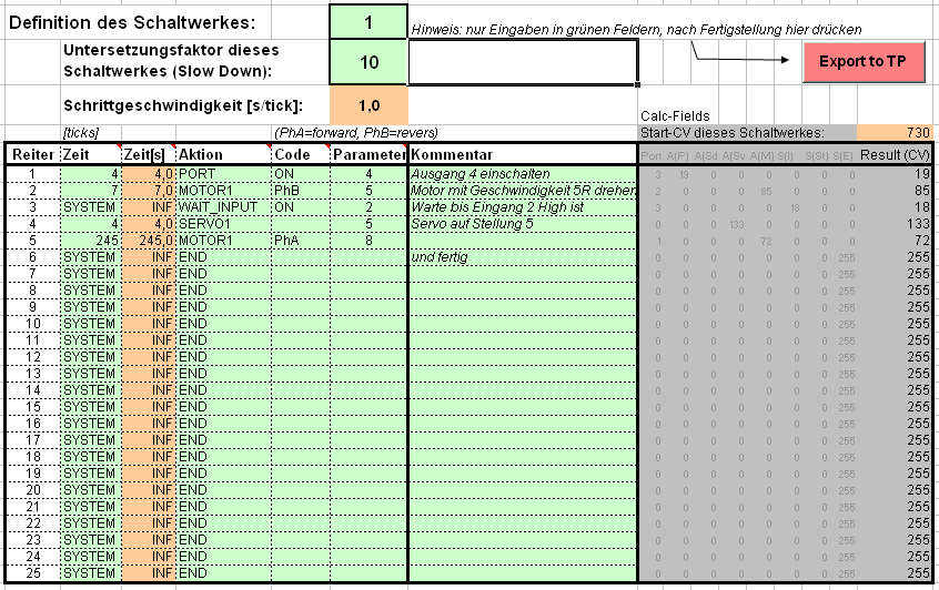
| Notes (Translations): Definition des Schaltwerkes = Definition of the control unit nur Eingaben in grünen Feldern, nach Fertigstellung hier drücken = Make entries only in the green fields. When finished, click here Untersetzungsfaktor dieses Schaltwerkes = Time slow-down factor for this control unit. Schrittgeschwindigkeit [s/tick] = Step speed [s/tick] Start-CV dieses Schaltwerkes = Start CV for this control unit Reiter = Cam Zeit = Time Aktion = Action Kommentar = Notes |
The entries are made here in clear text here (through selection with the mouse) and the resulting CV values are calculated with Excel. Moving or delaying cams is very easy with the "delete/insert new rows" functions in Excel. The time calculation and identification of the correct CV addresses happens automatically also.
To make a quick test you can connect the decoder directly to a PC (via an FTDI-RS232-TTL cable) and enter the commands for the actions directly. CVs are written directly and quickly using this method also.