DCC Sniffer
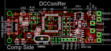
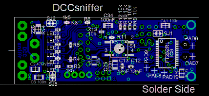
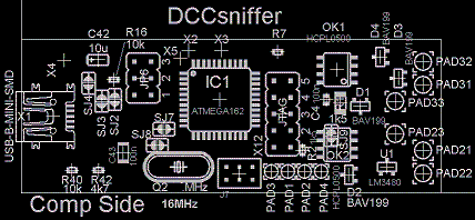
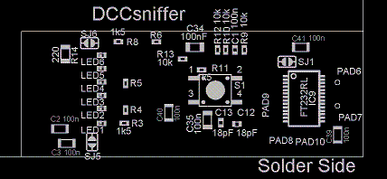
Layout
Assembly
- It may be required to fit different parts and/or close solder jumpers
depending on the planned application.
Please see the instructions at the corresponding software and in the schematics.
Generally spoken, DCC Sniffer is a board which is equipped mostly with SMD components,
therefore appropriate equipment and knowledge is required.
In the construction manual of OpenDecoder2
you'll find a description how to solder a QFP package.
- Assemble the components of the voltage regulator. (if required)
- Power the board with a current-limited power supply (either directly or through DCC-IN): please control the internal 5V supply.
- Assemble the LEDs and the associated resistors.
- Check whether each LED lights up when the corresponding pin (of the yet unfitted) processor is pulled to 5V. It is a good idea to use an 100 ohms resistor as 5V tip.
- Place the remaining components.
- Make an optical control with an microscope (important!)
- no power up the board with a current-limited power supply - power consumption max. 30mA.
- The plugs for ISP need not be soldered. - I use WRAP headers, plug them in the pcb and apply a little force to the side.
To prevent possible error, please proceed as follows:
Initial Power Up
-
After the assembly both built-in chips need configuration. This is done as follows:
- USB:
Download the adapted combi driver from FTDI. This driver offers two different modes:
D2XX enables the direct access. This mode is useful for the configuration with ftisp described below.
VCP emulates a serial interface - This mode is used during operation of the sniffer.
The downloaded archive is unpacked and then the USB connection is made. The operating system will now look for a driver. Use the driver just unpacked (FTDIBUS.INF).
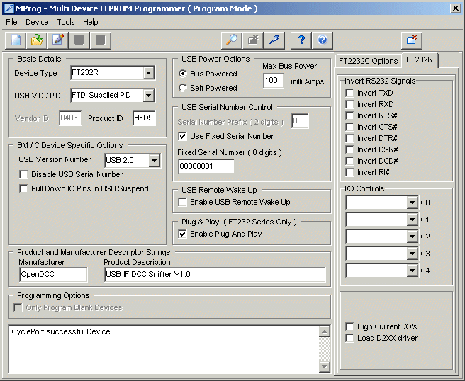
The configuration program MPROG is used to set the correct Manufacturer ID and product ID. Important: checkbox 'load D2XX' is not ticked.USB vendor ID and product ID VID: 0x0403 PID: 0xBFD9 Product Description: 'USB-IF DCC sniffer V1.0'
After the setup a rescan of the USB should be performed ('Cycle Device'). Now the board should be detected and installed as serial port. (using the VCP drivers). - AVR:
Now the Atmel processor is to be programmed. There are three data areas within the Atmel which needs to be configured:- Fuses: these are the basic setting bits, which determine the behavior of the processor.
- Flash: this is the program
- EEPROM: the permanent stored data.

In a first test we check whether the Atmel could be read. This can be done with the command ftipsv2 -Fr (read out fuses). The Atmega162 has the signature 1E 94 04
I've used ponyprog instead ftisp to write fuses and bootloader.
The fuses should be set to these values : LOW = 0xDF, HIGH = 0x98, EXTENDED = 0xF9; (for bootloader)
Now the board is ready for the application software. To download the application, disconnect the board and reconnect it again with pressed button. Now two LEDs should be on, indicating the active bootloader .
