OpenDCC - A Command Station for DCC
Overview
-
"Yet another Command Station? There are lots of them and You can buy them!"
 Yes, there are enough available central station around, also a number of do-it-yourself projects.
But when we tested them, we discovered some drawbacks:
at one station the number of the locomotives which can be driven (in wise self-restraint) is
too strongly limited, another station shows sporadic resets, yet another station uses
a bad prioritization of the DCC command stack, which makes not really usable for a larger
layout - why is there given a higher priority to the locomotive whistle than the brake instruction?
Yes, there are enough available central station around, also a number of do-it-yourself projects.
But when we tested them, we discovered some drawbacks:
at one station the number of the locomotives which can be driven (in wise self-restraint) is
too strongly limited, another station shows sporadic resets, yet another station uses
a bad prioritization of the DCC command stack, which makes not really usable for a larger
layout - why is there given a higher priority to the locomotive whistle than the brake instruction?
And some central stations are not really tuned for information flow-rate or short latencies. After a command CTS=off is sent back, then the received command is worked on and then the station goes on-line again. Doesn't matter, if you run only 4 locomotives...
A DCC message requires 6-12ms (depending on address and speed steps), therefore intelligent processing and priority scheduling is required to avoid problems when a number of locos is simultaneously acceleration or slowing down.
Our past central station had some of the above problems, thus we decided to build one on our own. Goals were first of all high throughput, intelligent processing of instructions and also a compact and concerning the price attractive solution, which can replace other command stations particularly in interaction with the PC. A small booster is integrated (just for a quick test of a loco or for programming).
The maximum throughput of DCC instructions was the highest design goal during the development. OpenDCC uses an intelligent refresh algorithm, which sends new loco instructions at high priority and then cyclically, whereby the repeat rate will decrease for selden used locomotives. Brake instructions got the highest priority, thus securing safety even when a lot of locos are running.
The dynamic assignment of the DCC commands garantees extremly fast reaction of connected mobile or stationary decoders, ev. if the command station is operated for a long time and with a lot of different locomotives. The host interface is independant from the local xpressnet, thus the PC needn't share the command interface with throttles. By using appropriate throttles (e.g. MFT or Multimaus®), the command station may be operated without a PC as well.
The board is universally laid out and can be used with suitable software as replacement for of the shelf stations (e.g. Lenz or Intellibox®) and/or feedback components (HSI88). Care was taken to make do-it-yourself easy: wide tracks, through hole components and DIL ICs, whereever possible.
When running a layout (especially in conjunction with feedback devices) an optocoupled booster should be used.
There is no keyboard (except "GO" and "Stop"), also the display is limited to a few status LEDs. With suitable software (e.g. rocrail) a layout can be driven however completely simply with a PC or a laptop.

|
|
The characteristics in the detail
- Power supply: The power is supplied by means of an external power pack with a regulated DC output. The power pack should be selected suitably the track width. For N scale 12-14V is recommended, for H0 16-18V.
- PC connection:
The connection is made either by USB
(VID: 0x0403, PID: 0xBFD8, Product Description: 'USB IF OpenDCC V1.2')
or serially (9-pin DSUB socket RS232 at back).
OpenDCC uses 19200 Baud, 8 bits, no parity, 1 stop bit (when running Lenz emulation).
The selection of the used interface takes place via solder jumper on the board.
(assembly alternative and/or by jumpers).
In the case of use of the USB interface a VCP driver is to be
installed on the PC side.
The protocol used on the interface depends on the loaded software. Currently there is a universal software, which can be selected by jumpers to act as Intellibox PX50 or HSI88 (Lenz V3.0 is available as compile option). Additionally, an implementation of miniDMX is available.
The software can be updated over the normal interface, no special programming adapter necessary.
Safety reference: It is implemented (contrary to some commercially available solution) a full compliant RS232 interface with correct levels, OpenDCC is not galvanically separated from the PC. Thus the electrical insulation, as required for toys, is waived. For the reaching of the protection separation an optocoupled booster is to be connected at the outlet side. See also NEM 609. - Connection to the layout:
- There are two DCC outputs, programming track and main track.
The output to the main track is fed by an intelligent data prozessor, thus getting the optimum performance
out of the DCC protocol.
The used plug system is Wago mini, grid 3,5mm; (the soldering plug has the part.no. 734-164, the plug-in part the number 734-104;) Alternatively also commercial c-clamps with a grid of 5.04mm are possible. Both outputs are short-circuit-protected (programming track 0.5A, main track 1.5A), whereby the permanent current which can be taken is not to exceed 1.0A. This can lead to a thermal shutdown. - Opto coupler input and output for emergency stop input and shutdown message to other components. The plug system is again Wago like above.
- Three S88 lanes are supported, these may in sum with 1,5A on the 5V be loaded, if the equipped 5V regulator is capable of supplying the current (see notes in the schematics). The S88 lanes may connected alternatively as usual pin row or as RJ45 plug (Pinning according to the standard S88-N). The wiring with ethernet cables (CAT-5) is recommended, in order to minimize the interference couplings on the S88 lanes.
- Hint for Wiring the Layout: The track output of OpenDCC swings between for instance 0,3V and 14,7V related to the power pack mass. Therefore it is not allowed to implement any ground return path from the tracks. This can happen together with feedback modules either direct or through the computer. It is strongly recommended to use an optocoupled booster in such scenarios.. See also: Howto wire a layout.
- There are two DCC outputs, programming track and main track.
The output to the main track is fed by an intelligent data prozessor, thus getting the optimum performance
out of the DCC protocol.
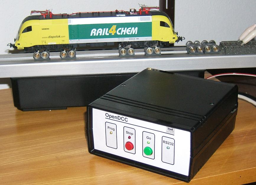
- Control elements and indicators:
- LEDs:
Display: •
LED1, orange
PROGin normal operation: off: everything okay flashing: too many instructions during programming: permanently on: programming done flickering: ACK is currently read flashing: error during programming •
LED2, red
STOPon: DCC was switched off by tracers. flashing: emergency stop. red and green on: speed 0 •
LED3, green
GOon: everything okay flashing alternative with STOP: Error in output stage, either short curcuit or too hot. •
LED4, green
RS232This LED indicates the condition of the data link to PC:
slowly flashing: no connection continuously bright: connection established bright, short breaks: data transmission fast flashing: data transmission blocked (fifo full) - Tracers:
Tracer Operation STOP: First stroke: the system is halted, the track will be powered, but the speed is set to 0.
Second stroke: track power is switched off (emergency stop).GO: Track Power is turned on. - By means of a small adapter pcb external throttles based on Xpressnet™ could be connected. PC interface and Xpressnet™ interface are operated simultaneously.
- LEDs:
- Programming interface:
- JTAG header: plug X4, this is the usual 10 pin connector, grid 2.54mm
- Ponyprog header: second RS232 plug, usable for Ponyprog, a free download tool available at www.lancos.com Note: please invert the RST-Output when configuring ponyprog.
- ISP header (6 pins, JP3): Here the usual programming adapter can be connected.
- The Software can be updated without opening the box and without the programming adapter either through RS232 or USB.
- Other ports:
-
RS485 header for DMX Control;
The connection on the board takes place with c-clamps.
(Note: the usage of the DMX-Decoder is recommended) - Technical Basis:
-
OpenDCC is run with an Atmel AVR microprocessor. There are two version (based on atmega32 and on atmega644P
for Xpressnet). However, I recommend in any case the use of atmega644P. This porcessor, a small booster
(H-Bridge, based on STM L6206) and some smaller peripherals is integrated on a board with 120*100mm.
The layout is twosided, broad tracks and through hole components allows for easy soldering.
The software is written in modules with C (using gcc = WinAVR) and is available as open source. - Testing:
- the following tests were so far accomplished:
- HSI88 mode, operation with traincontroller by RS232 and USB. Control of bit positions, control of timing and signals
- HSI88-Mode: operation with railware 5.01 and USB (Alex)
- Lenz mode: Baud rate change-over, mode change-over
- Lenz mode: operation with traincontroller and 28 speed steps.
- Lenz-Mode: Accessory commands
- Lenz-Mode: operation with P.F.u.Sch. and 28 speed steps, light, functions
- Lenz-Mode: Decoder readback in CV-mode with P.F.u.Sch.
- Lenz-Mode: Test of S88 feedback with railware (Alex)
- Lenz-Mode: Programmieren der Opendecoder (ab V0.14)
- Intellibox-Mode: operation with TC (mit RS232 und USB inkl. BABI) on a midscale layout (16 boosters, 320 feedback sections)
- Intellibox-Mode: Test of S88 feedback with railware (Alex)
- Intellibox-Mode: operation with Railware and 28 speed steps, drive, switch, function
- Intellibox-Mode: test with OpenDecoder
- Intellibox-Mode: programming with TrainProgrammer from www.freiwald.com and railware (Alex)
- Intellibox-Mode: operation with srcpd - switch and drive
- DMX-Mode: light control for room light
- Limitations / known bugs:
-
The position of switches is not permanently stored in OpenDCC. At power up, all turnouts are reported to be in
"position green (= 0)". During operation the switch positions are however stored.
If a PC program really relies on the positions, please use this workaround:
call ALL switches before steering the layout.
Documents / Links
- Commands (Intellibox-Mode)
FAQ and version history
construction guide
USB installation
Software install and update
Guide: compiling the system
Schematic V1.4 Layout V1.4
Source Code: OpenDCC_V014.zip (contains .HEX and .EEP files)
- links:
Other DCC centers in the net:
rkdcc of Rainer Keil
MobaSbS of Patrick Urban
Franken DCC of Oliver Spannekrebs
PC as DCC central station in dutch
DDL of Torsten Vogt
DDW
MiniDCC
http://www.tinet.org/ small central station with PIC
Other DCC stuff in the net: MERG
MRBus Feedback and Accesory with open protocol
JMRI DecoderPro