Setting OpPanel To operation, Install |
This Page is under Construction
hardware configuration
-
The card is equipped with 3 sockets and a jumper.
- the board will run off 3,3V.
- With a GBMBoost, the 3,3V can be taken there.
- If the board runs from an FTDI-TTL cable (3,3V type),the 3,3V can be taken there.
- If you want FTDI + GBMBoost, one 3,3V supply need to be open.
- That's the jumper.
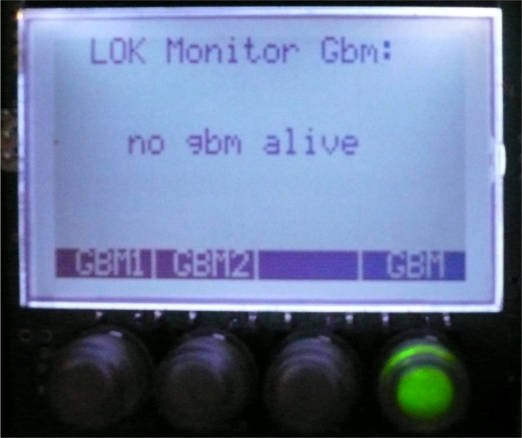
- The GBM16t boards are connected to sockets 1 and 2. GBM1 is on the socket 1 and GBM2 is on the socket 2, OpPanel on socket 3.
- The GBM16t boards are connected to sockets 1 and 3. GBM1 is on the socket 1 and GBM2 is on the socket 3, OpPanel on socket 2.
- The GBM16t boards are connected to sockets 2 and 3. GBM1 is on the socket 2 and GBM2 is on the socket 3, OpPanel on socket 1.
The jumper is used to select as the power source, or the FTDI connector or the GBMBoost.
-
The three sockets are respectively on the right of the board the FTDI socket and the socket to connect to GBMBoost, on the left of the board the socket to connect to the loading tool ATMEL (AVR PDI).
The board can be equipped with a socket for Xpressnet and with a socket for BiDiB labelled BoBus. Fianlly an emplacement is provided for a USB connection.
Installing the links
Software keys refer to GBM1, GBM2. The GBM are referenced to the socket numbers as labelled on the GBMBoost board in ascending order . There is no specific location for OpPanel.
example:
 |
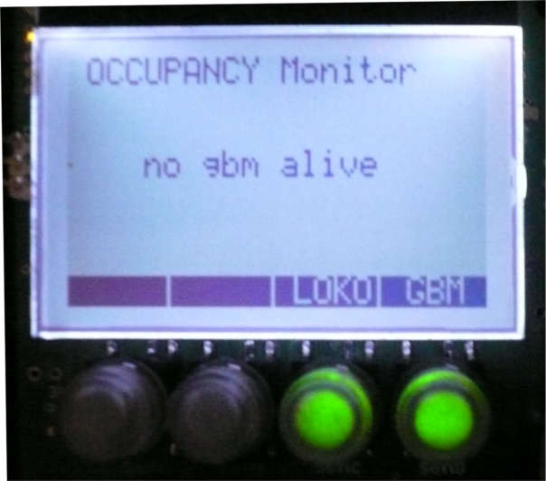 |
This is the case also if there is no DCC on GBM16t.
Initial Software Configuration
- de -100 LED éteintes à
- +100 écran éteint
- adresse # (4k range 0.. 4095)
- valeur (byte range 0 .. 255)
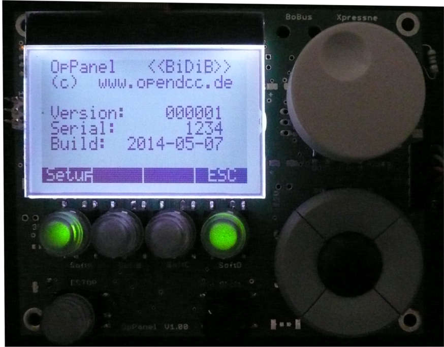
To access the menu, press the center button of "Navimec": referencing informations are displayed. Then select Setup, and navigate through the screens with the up / down Navimec. |
|
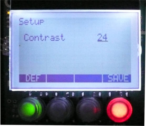
In the example on the right, the contrast value was changed by turning the rotary knob. The DEFkey again returns to the stored value before the change. Save memorize the actual value. |
|
The parameter list is as follows: (Their use depends on the software modules used)
| Brightness | de 0 à 100% | ||||||||||||
| Contrast | de 0 à 63 | ||||||||||||
| LED vs. Back, | change le rétroéclairage en relatif aux LED |
||||||||||||
| Bright-Night | |||||||||||||
| Def. Connect | none, XP, WRP | ||||||||||||
| XP Slot | AUTO, M:01 .. 31 | ||||||||||||
| PC ID: | 00 .. 31 | ||||||||||||
| DCC Default | 14, 28, 126 | ||||||||||||
| Stop Key | Stop, Off, myloc (MAKES_OFF, MAKES_STOP, MAKES_STOP_MY_LOCOS) | ||||||||||||
| Knob | as DC, as AC | ||||||||||||
| Knob Push | Speed 0 ou Emergency Stop | ||||||||||||
| Switch Time | 100 .. 9950 in 50mS steps Indicates the "turnout_delay" value to operate the switches |
||||||||||||
| Splash Screen | from 0 to 9900mS in 100mS steps, Default: 1000mS | ||||||||||||
| int.EEPROM |
|
||||||||||||
| int. RAM | Same as above for RAM |
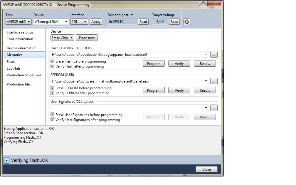
Installing a BootLoader
The Board should be equipped with a BootLoader. If this is not the case for a new installation, the boot loader can be installed on the board using the Atmel tool AVRISP by connecting it to an AVR PDI interface.
The BootLoader is available here download.
The BOOTRST fuse must be set onto BOOTLDR.
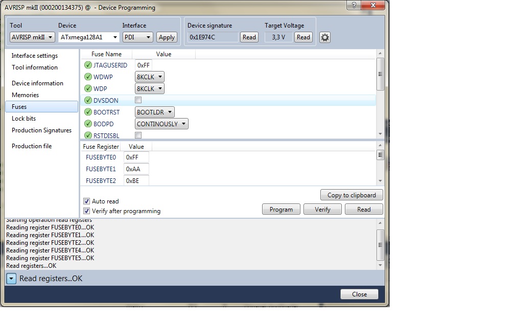
Then just start the download of flash memory with the executable file .hex of the boot loader
Updating the software
-
Refer to the corresponding section in the firmware_update page.