S88 Feedback module for IR reflex detector
Introduction
- For any kind of automation sensors are required to monitor the actual situation.
Well known and proven are electronic occupancy detectors in each section of the layout together with
accordingly prepared vehicles. (axles with resitors).
- mechanical: The moving car operates eg a switch or a pressure sensor.
- electric: The moving car acts in any way at this point electrically (ie conducted) – eg by electricity consumption or electrical connection.
- electronical: The vehicle acts in any way at this point electronically - for example, by its metal (change frequency of an oscillator) or by its components (eg RFID)
- optical: The cart is detected by light (either direct view or reflection).
- magnetical: The car is detected by means of magnetic field, for example, reed contact or hall sensor.
- acoustical: The car is detected by ultrasound. Depending on the method used different grades of security and error tolerance can be acheived. Even recognition of individual car types is possible. Example: with the help of a light barrier (direct light) and the characteristic patterns when a train moves by it is possible to automatically separate passenger trains and freight trains. A barcode could be read as well as an RFID chip.
However, for certain operations and situations additional sensors are required for getting a feedback with higher resolution. They can be separated accordingly to their mode of operation:
Reflection light barrier
A relatively inexpensive method for detection are reflective light barriers. These are mounted in the center of the rails and detect the reflection by a train passing by.
PCBs
 |
 |
 |
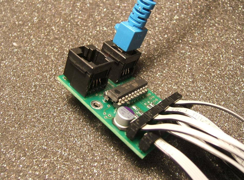
| Controller with - processor attiny26 - S88-n connection - 8 sensors connected |
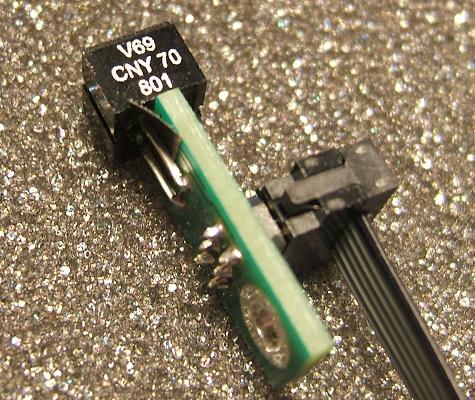
Sensor solder side |
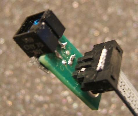
Sensor component side |
Control
- The diode should be operated with a current of 20mA at a voltage drop V(forward) of 1.3V.
The resistor calculates 180Ω.
According to the data sheet of the CNY70 the collector current at the output with an object in 10mm distance
is approximately 50µA. Thus, with 47kΩ pullup resistor a reasonable voltage (0 to 2.5V) at the input of the
attiny will result. The pullup is connected to an auxiliary voltage of 2.5V.
The photo transistor will not only be activated by the reflected light, but by the overall ambient light as well. To ensure reliable detection, the influences of the ambient light (eg, 50Hz hum from the room light) must be eliminated. This can be achieved by an accordingly protected installation and on the other hand by appropriate filtering. This is done by sending a certain code to the emitting diode and checking at the recipient, whether the fluctuation of the measured light intensity matches this code. Here a very simple code'01010' is used. The symmetry in the code smoothens slow fluctuations.
Evaluation of the sensors
-
The measurement is performed with the integrated ADC of the ATtiny26. This converter requires 13 cycles for
one measurement at a maximum clock (in the case of 8-bit accuracy) of 1MHz.
5 measurements are performed for each channel:
| Measurement | emitting diode | measured values | |
|---|---|---|---|
| 1 | off | A1 | |
| 2 | on | B1 | |
| 3 | off | A2 | |
| 4 | on | B2 | |
| 5 | off | A3 | |
| mean values: | A=(A1+A2+A3)/3 | B=(B1+B2)/2 | |
This evaluation is done every 10ms for a sensor. Assuming a train traveling with 50km/h (scale H0). it will travel 16cm in one sec. Thus, the query interval is 1.6mm.
Because the emitter diode is only turned on during the measurements in phase 'B', the pulsed power consumption of 160mA will be reduced. The supply of the diodes is decoupled with an RC lowpass to prevent ripple on the power supply of the s88 bus.
The measured values are debounced against 'flickering' similar to the s88 keyboard.
Schematic
The IR LEDs are switched by a MOSFET. The supply of the LEDs is filtered by with a lowpass to prevent the 160mA strong pulse disturbing the power supply on the S88 bus.
The connection of the S88 bus is performed (similar to s88 keyboard by the USI-register.
The sensors are mounted on small pcbs (9*20mm) and connected with 6-pin ribbon cables (RM2) with the board. The small grid (2mm) allows for small sensor boards, which are easy to install.
Layout
 |
 |
|
||||
 |
 |
|||||
| Component side, master PCB | Solder side, master PCB | |||||
Installation of the sensors
- Horizontal mounting
The sensor is mounted 'normally', the board will be screwed from the underside of the layout. The cable runs downwards. - Vertical mounting
The sensor is mounted on the side of the pcb, the pins are connected from the side. (the pins almost pinch the board, please take care to ensure that the terminals A and E do not cause short circuit) The board will then be mounted through a hole, the cable runs to the side. - Alternatives (by Jan):
'As a more flexible alternative to CNY70 we used SFH309FH and SFH409 in the same circuit (see below). This increases the total range (up to 5cm) and the installation is easier.'
The sensors are mounted on small pcbs with the dimensions 20*9mm. These pcbs are connect with pinheaders (2mm grid) and ribbon cable with the master board.
The sensor board can be mounted in 2 ways:
Software
- The connection of the S88 is performed by using the USI register, see the
explanation for the S88 keyboard .
The analysis of IR sensors is done every 10ms. The measurements per channel will be launched successively after each other. Each measurement lasts 13µs. These measurements are interruptible - that's why they are called in the main program loop.
Flashing the software can be done with ponyprog, there is a 6-pin ISP header on the board.
palmavr is a tool to determine the fuse bits Here: High:F4, Low:C4
Important Note: if the attiny26 is programmed in the target hardware, s88 lines must be disconnected during programming.
Download:
V0.01 (zip, contains source and compiled hex file)
V0.03 (bugfix, avoid bouncing (von _hk_)
V0.04 (bugfix, better mux settling)
Links
- Schematic for IR refective sensor with CNY70, LM567
(auf PLL-Basis)
Kit from ELV