Setting to Operation: BootLoader |
This Page is under Construction
OpPanel has a host interface for updating the firmware and for easy configuration. The PC is connected via a FTDI USB cable 3V3(important) to the ATXMEGA serial port. A virtual COM port is initialized
Starting the BOOT
- LED 4 LED_POWER
- LED 3 LED_MSG
- LED 2 LED_STATUS
- LED 1 LED_PROG
Before powering up OpPanel press and mantain pressed the shift / stop buttons, the boot loader is the active and a firmware update can be performed.
The LED situated to the left of the display and on the top of the board are upwardly respectively;
The POWER LED is illuminated when the boot program is started, ie when the keys shift + estop are released.
The Message LED is lit if both shift and Estop buttons are pressed during powering up.
The status LED flashes briefly for each byte transmitted.
The PROG LED remains off.
Firmware-Update
- e<CR>: choose the EEPROM and send .hex file
- f <cr>: to select the FLASH memory and send the file .eep
- x <cr>: End and start the application if it exists.
The bootloader communicates using the AVROSP standard protocol at 19200 baud, 8N1. More information can be found in the instructions of the remote control MFT.
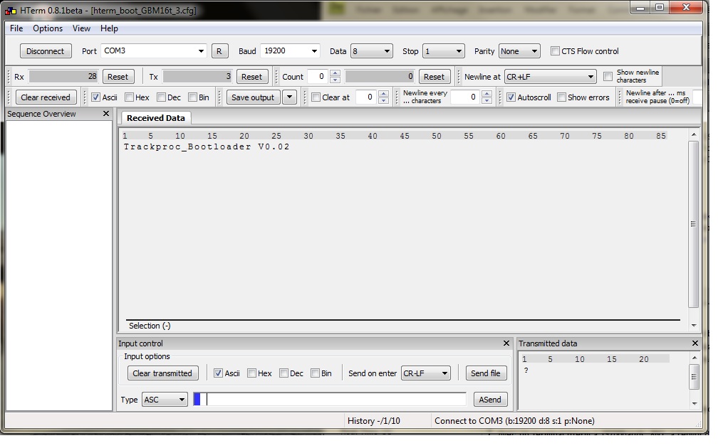
With hterm terminal 19200bauds, 8N1, when sending ? <cr/lf> (line feed carriage return) the bootloader responds with its version number. Bootloader V * * We can then send one of three commands:
Example
-
In the example below OpPanel is powered by the FTDI link. The cable is plugged in while the two buttons are pressed. Then the hterm terminal is opened with the right configuration. When sending a question mark OpPanel responds Trackproc_Bootloader V0.02.