S88 Keyboard
Introduction
 There are quite a lot of accessories and moving objects on a model railway layout, these are often operated
either automatically or through local keys. Tyically, the equipment is controlled by decoders, which
are controlled by the command station and the computer.
So we need to forward the local keypress to the computer. I have designed a very simple S88-feedback device,
which is either directly connected to eight buttons or to a small numeric keypad. The keystrokes
are debounced and fed to s88 bus with adjustable hold time.
Also, the feedback a booster failure can be monitored.
There are quite a lot of accessories and moving objects on a model railway layout, these are often operated
either automatically or through local keys. Tyically, the equipment is controlled by decoders, which
are controlled by the command station and the computer.
So we need to forward the local keypress to the computer. I have designed a very simple S88-feedback device,
which is either directly connected to eight buttons or to a small numeric keypad. The keystrokes
are debounced and fed to s88 bus with adjustable hold time.
Also, the feedback a booster failure can be monitored.
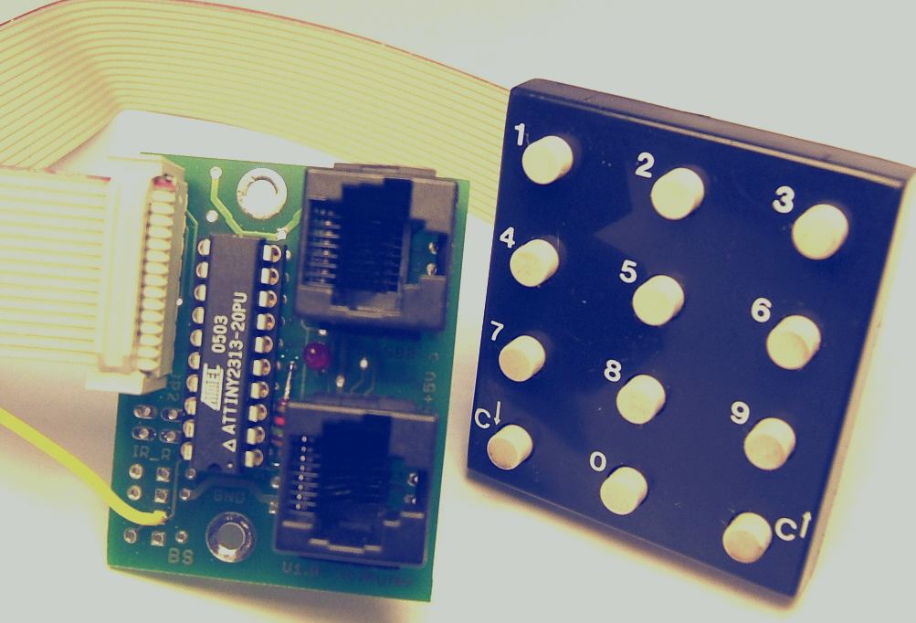
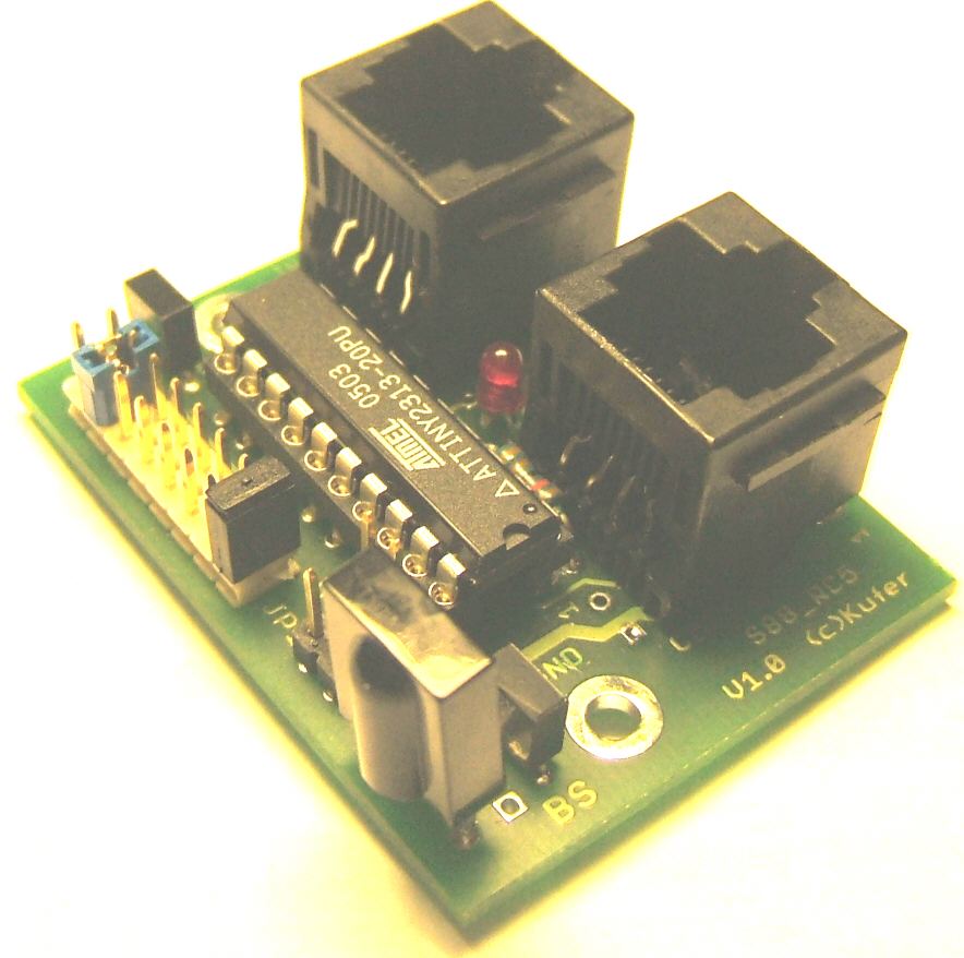
The module is a small circuit board with only one ATtiny2313 and is therefore *very* cheap. The S88 interface is either accessible with conventional pin headers or with network cables in accordance to the standard S88-N.
Curcuit
The schematics is relatively simple: the entire logic is implemented by using one ATtiny2313. It runs on an internal clock of 8MHz.
The S88 connection is done the help of the USI (Universal Serial Interface), this is a shift register on the chip. This shift register is inserted in the S88 data stream. The connection to other modules is either in the standard S88-N or alternatively with 6 pins.
Additionally, an IR receiver can be fitted, so that receiving commands from a TV remote is possible. Here you will find information on the sampling technique used.
The connection of the tracers is provided through a 16-pin ribbon cable. The pinning is alternately GND - key, thus the cable easily can be spliced and connected to the tracers a the specific location. Each tracers acts against ground, the required pullup is implemented inside the Attiny. There is no protection circuitry, so only buttons or optocoupler outputs should be connected. Do not connected any signal from the railway lines, this would destroy the processor.
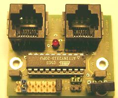
Layout
|
 |
 |
| Component side | Solder side | Components |
Connections
-
The connection to the S88 bus is done with CAT5 cables according to the standard S88-N (5V).
If a read cycle on S88 bus is detected, then the LED is activated for a very short time - thus the LED shines
weak, if S88 is active.
When a button is pressed, the keystroke will be debounced by the software and hold for approximately 1s.
As long as the button is pressed, the LED is fully activated, thus giving a direct control of the button and
and the connection to the module.
m Taster möglich.
-
Connection of conventional tracers or optocoupler outputs
The device can read 8 inputs, these should act against GND. Every second terminal on the connector is GND, so it is possible to individually conntect each input simply by splicing the ribbon cable. For example, the first tracer must be connected between pin 1 and 2 of the cable.
In this mode the module uses 8 feedback addresses, jumper 1 is not fitted-Pins for tracer GND 1 2 Key 1 S88 detector 1 GND 3 4 Key 2 S88 detector 2 GND 5 6 Key 3 S88 detector 3 GND 7 8 Key 4 S88 detector 4 GND 9 10 Key 5 S88 detector 5 GND 11 12 Key 6 S88 detector 6 GND 13 14 Key 7 S88 detector 7 GND 15 16 Key 8 S88 detector 8 - Connecting a magnet field detectors
Besides the normal outlet for traces there is a pin header row for 5V. This allows to directly connect a hall sensor with a three wire pin header cable. Switches, tracers, optocoupler and hall sensor could be mixed. -
Connecting a mini keyboard (matrix)
The module can also handle a small numeric keypad - these are often quite cheap. The keypad used here is available for 0.95€ at www.pollin.de.
This keypad has 12 keys, which are organized in two columns and 5 resp. 7 lines. There are 9 wires required: 8 lines are used on the standard connector, and in addition, the supply line of the IR receiver is used (of course, IR receiver must not be fitted in this case)
The processor generates the scan signal for the columns and reads the row lines.
In this mode the module uses 16 s88 addresses. Only the lower 12 addresses are used. Because of the easier assignment in the PC software the length of the s88 device is set to 16. Jumper 1 is closed.Connection of numeric keypad (Samwell) n.c. 1 2 Pin 2 n.c. 3 4 Pin 6 n.c. 5 6 Pin 7 n.c. 7 8 Pin 8 n.c. 9 10 Pin 9 n.c. 11 12 Pin 10 n.c. 13 14 Pin 11 n.c. 15 16 Pin 12 Connection IR receiver Pin 1
The keys are assigned as follows the s88 feedback addresses:
Mapping of numeric keypad (Samwell) Key: 1 2 3 4 5 6 7 9 0 Cv C^ S88 Detector 1 2 3 4 5 6 7 9 10 11 12 13 14 15 16
Either standard buttons or a small matrix keyboard can be used. This is distinguished by JUMPER 1.
Notes on the software
- keyboard input:
All states of port I/Os with tracers are read by the input routine into a vector. This vector is then processsed bitwise. The state engine does the debouncing in both directions as well as an additional hold memory of one second for the activated state. As long as the output vector (current_message) of the state machine contains actived states, the local LED is lit to give a visual feedback. - message handling on S88 bus:
The S88 bus is connected to the USI interface of the processor. This interface offers 8 bits, shifted with an external clock. When shifting is done an interrupt (USI_OVERFLOW) occurs. To keep the bit length of the module freely programmable, the interface is programmed to generate an interrupt at each clock edge. Upon the rising edge the current bit is copied to shift register (shift_reg) inside the SW. Upon the falling edge the next bit to be sent is copied to the output buffer. The length of the SW implemented register is determined by the variable shift_size. Thus this routine can handle feedback lengths from 4 to 32 bits.
Each interrupt turns on the LED for a short time, thus the read of the s88 bus can be monitored.
Documents / Links
- Download: S88_Keyboard_V0.02.zip
S88_Keyboard_V0.06.zip
Numeric Keypad from Pollin (Samwell).pdf
Notes on the RC5 receiver software
Explanation on RC5 code of the remote control
extern: S88 Logger