OpenDCC GBM16: BiDi/Occupancy-Detector
Introduction
 This project comprises a 16/64-fold track occupancy sensor with integrated BiDi-capability.
Previous restrictions with respect to the
combination of occupancy detection and Railcom® now do no longer exist.
Highly integrated computing power and multiple interfaces
allow for exploiting the full potential of BiDi. For BiDi-detection, a completely new approach based on systemtheory and digital signal
processing has been introduced.
This project comprises a 16/64-fold track occupancy sensor with integrated BiDi-capability.
Previous restrictions with respect to the
combination of occupancy detection and Railcom® now do no longer exist.
Highly integrated computing power and multiple interfaces
allow for exploiting the full potential of BiDi. For BiDi-detection, a completely new approach based on systemtheory and digital signal
processing has been introduced.
Both the PC and the DCC-command station make advantage of this new concept: the PC is able to retrieve detailed information on the actual location of each loco, whereas the command station may track which loco has already acknowledged DCC commands and in turn is able to perform an optimization of the DCC signal to be put on the main. Moreover, decoders that return information on actual speed may help to improve the precision of time-distance-simulations within PC software applications.
What would this be good for? The control program already should know - based on its tracking of trains - where each of the trains is located. Information on the direction of each train can be visually verified. So why BiDi and detection of direction?
A simple example shall demonstrate this: Imagine a modelrail-exhibition with a big club layout. All is running fine; there are 60 trains up and running. Suddenly, a control program crash (or some dork switches off power by stumbling over power cable or accidentally hitting the main switch) - dang! - the watchdog kicks in and all is down. Power up the PC is easy, but the current status train <-> track is lost. So someone needs to crawl underneath, check the yards, telling someone to type in the information. With BiDi, this is not longer necessary; however, only BiDi with detection of direction saves you from crawling!
Features
- 16 sensor inputs, each able to carry a max. of 3A constant current, peaks up to 4A.
- BiDi-feedback and und track sensoring integrated in one component, extremly small voltage drop of only 0,3V on the main (Note on availability of BiDi: see FAQ)
- No extra power-supply required (power from the main track, small consumption)
- Local display of current occupancy and existence of BiDi-traffic by integrated LEDs
- Display of current status (Power, connected, message) with LEDs
- Configurable Memory (threshold) of occupancy status
- Freeze in case the command station is shut down
- Booster failure report
- Configurable Feedbackaddress
- Configurable per DCC or USB
- Optional: Integrated terminal loop using sensor tracks
- Integrated Optocoupler, main fully separated from command station and PC
- Connection to PC over USB, to command station over BiDiBus, Xpressnet or S88-N; PC and command station may be connected simultaneously
- Occupancy detection:
- Separated measuring of current on each connected track, fast parallel measurement
- Configurable sensitivity
- High sensitivity for use of resistor-axes
- Flicker-prevention by intelligent filtering
- When using extra power-supply, measurement is possible with no command station connected
- BiDi:
- Intelligent BiDi-interpretation of all 16 channels using locale detectors, with multiple channels in parallel and simultaneously. This allows for train identification (CH1-messages) on newly occupied tracks and independent analysis of already occupied tracks in parallel
- Integrated detection of direction
- Specialized bit-identification with filters and eye-detection allowing for compensation of message disturbance
- Base units GBM16T and GBM16C for 16 sensor inputs (common voltage), expandable up to 64 inputs by up to 3 extension units (16 inputs each with common voltage, extension units mutually separated voltage).
- Up to 16 boards can be combined into a large feedback system.
- Extensions:
16-fold track sensor with interface: 80 x 100mm 16-fold track sensor extension (GBM16T):
(max. 3 extension units may be connects)52 x 100mm
Layout
-
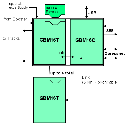
GBM consists of two components - a track sensor unit (GBM16T, T='trackproc')
and a control unit (GBM16C, C='controlproc').
The units are on the same board but may be separated and connected by a 6-pin cable.
The control unit may drive up to three additional
(a total of four) track sensor units which are connected by 6-pin cable.
The track sensor unit is supplied from DCC signal and takes care of track sensoring (using current measurement) and BiDi-analysis. The control unit communicates with the PC and in parallel with the command station. Track sensor unit and control unit interact over fast data-coupling.
Connectors
- DCC Input from booster
- DCC Output to tracks, with single or double (recommended) track connection to the sensors. Additional switches are not required. Connectors are accessible by plug or may use screw terminals.(System RIAcon 3.5)
- Additional power-supply over Mini-USB-B (optional, separated voltage(!)) or screw terminal.
- Xpressnet over RJ12, two jacks for easy system integration
- S88-N, RJ45, input and output
- USB, over virtual COM-Port for direct feedback to PC. Various protocols may be emulated.
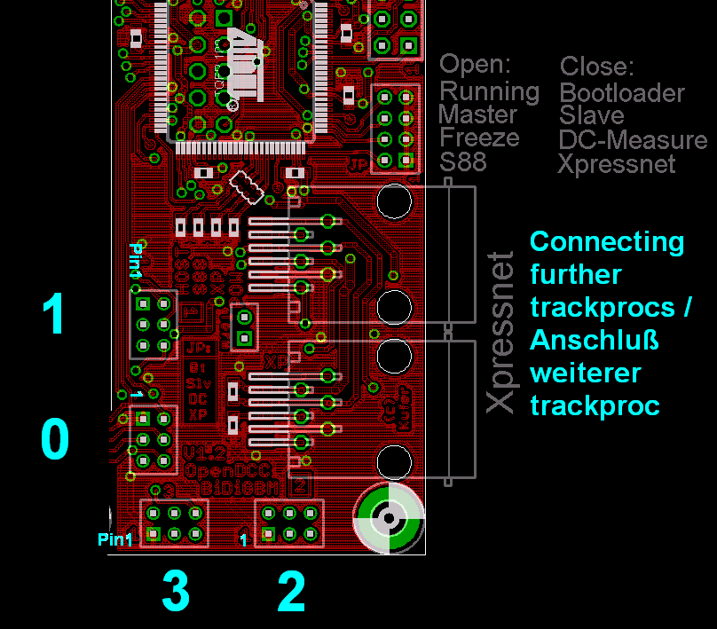
Display
- Trackproc has 16 + 4 LEDs for display of internal status:
- LED POWER:
LED is on with reduced brightness (50%), whenever a message is transferred to the control unit (e.g in case of a status change) LED brightness is temporarily increased. - LED DCC:
With no DCC-signal detected, the LED flashes. Once the DCC-signal is recognized, the LED is on with reduced brightness (50%). - LED PROG:
Displays the programming mode the GBM is in. - LED BIDI:
If a cutout is detected on the input signal, the LED is dimmed (but on). Whenever a feedback from the track is detected, the LED flashes brightly. - LED POWER:
LED is on with reduced brightness (50%), in case of errors, the LED flashes (with error code). - LED XP:
Off in case no XPressnet is connected. In case of connected and active XP the LED is on with reduced brightness (50%), in case of errors, the LED flashes (with error code). - LED S88:
Off in case no S88 is connected. In case of connected S88 the LED is on with reduced brightness (50%), in case of errors, the LED flashes (with error code). - LED MSG:
LED flashes in case the GBM actively sends out an occupancy message.
Controlproc has 4 LED for display of internal status:
Usage
-
GBM is able to generate occupancy messages and may transmit additional messages like, for instance, addresse, CV or
current speed. Depending on connection and emulated protocol there are various things to consider:
Occupancy:
- In order to transmit occupancy messages, the following is possible:
- Transmission using S88 Bus:
S88 is a simple serial shift register without explicit addressing. The address of a sensor is given by its position within the feedback chain.
The GBM16C control unit is added to the feedback chain of the S88 bus and represents a number of feedback slots defined by its chosen position. Upon switching on, GBM16C checks the number of connected track sensor units GBM16T. For each GBM16T recognized 16 S88-sensorbits are generated and integrated into the S88 datastream (following the order of detection). In case there is no GBM16T connected to one of the GBM16C interface, consequently no S88-sensorbits are generated.
- Example: To a GBM16C two GBM16T are connected on interface 0 (the hard wired one) and 2:
32 S88-bits are used, with the first 16 bits for GBM16T on interface 0 and the second
16 bits for GBM16T on interface 2. GBM16C uses 32 sensor slots.
- Transmission using Xpressnet Bus:
BiDi messages and track sensor messages can also be transmitted over Xpressnet bus as implemented bynew, effectiv commands. Those additional commands only work with an OpenDCC command station; other Xpressnet-capable command stations will not be able to interpret them appropriately.
Address-mapping of sensors is done by the feedback address configured for the GBM16T used with the advantage of such address being freely configurable. Extension of the feedback system has no impact on the address chosen; in particular, it will not be lost. The address does not depend on any cabling or topology. However, it has to configured manually, which is error-prone.
... Some text missing here ...