OpenDCC - Command Station for DCC - Xpressnet Adapter
Introduction
-
Xpressnet™ is a bus system for model railways to
interconnect input devices, computer interfaces and stationary decoder or feedback detectors.
Many commercial input devices (including the multi-mouse from Roco) are based on this bus.
The following adapter enables OpenDCC to interface to Xpressnet devices.
Schematic
- Power supply:
Xpressnet devices need a power supply of 12V. This voltage is created with an linear regulator from the supply of OpenDCC. On large Xpressnet installations, however, this power supply may be overloaded. In this case, the 12V should be generated with a powerful external power supply. The fuse F1 must be left out in this case.SJ1 should be left open. - RS485 receiver and transmitter:
Xpressnet uses a half-duplex RS485 connection. The baud rate is 62.5 kBaud, 9 bit are used, no parity, one stop bit. The chip Max485 (or Max481) takes the data from the serial interface of the processor and converts it into the R485 differential signal.While not required, it is strongly recommended that slew-rate limited transmitters be used to minimize high frequencies on the bus, and thus help avoid possible termination/reflection issues. A LED displays the transmission direction (normally not needed).
By testing different transcievers I found that the differential lines of RS485 may come to an undefined state, if neither master nor slave is sending. A pullup resitor of 1k5 to 5V on line A and a pulldown of 1k5 to GND on line B is recommended.
If the circuit is to be used as listener only, the receiver is permanently enables by closing the solder bridge SJ2.
The circuit consists of two parts:
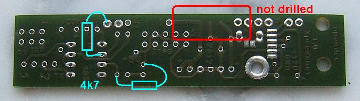
Layout
 |
 |
| component side | solder side |
Installation and necessary changes at the command station
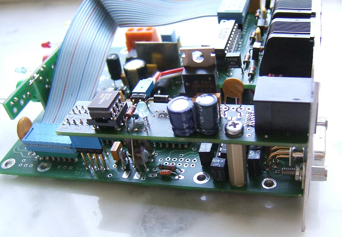
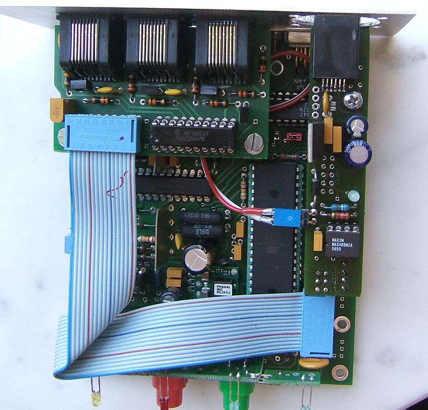
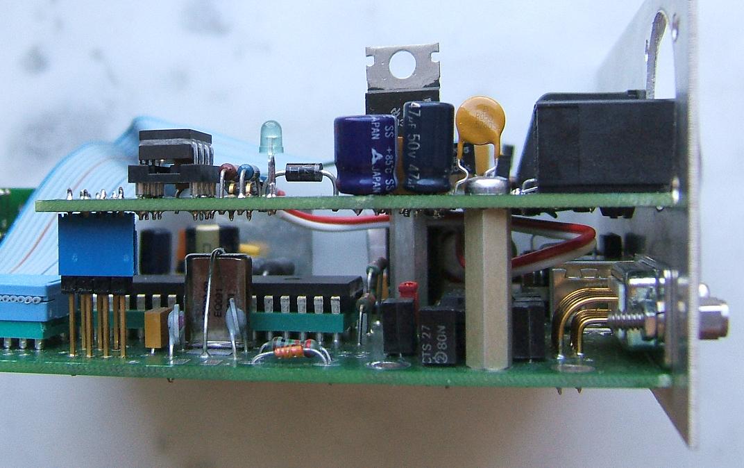
The adapter could be plugged on the pin headers for JP1 and JP2 boat and on the interface for ISP. Only the power supply (+15 V) for regulator for Xpressnet must be connect with a separate wire from the power supply plug of the command station. I'm using long wire-wrap pin header to get a distance of 20mm between the PCBs.
The Xpressnet interface is accessible directly from the rear side of OpenDCC. A corresponding cutout in the rear panel must be created.
Necessary changes:
The processor Atmega32 of OpenDCC must be replaced by an Atmega644P, to support the second USART. Important is the suffix P (PicoPower), only this type contains two USARTs.
Of course, this new processor requires the corresponding software to be loaded.
For the installation on the model railway sockets are recommended.
Test, first power up
-
After mounting of the parts visually inspect everything exactly and wash away remaining flux with alcohol.
Now power up the adapter and check the output voltage. Only after this Xpressnet devices should be connected. The Roco Mulitmaus reports Err13 when it cannot connect to the command station.