OpenDCC, Details on the Software, Points-feedback
Introduction
- When switching points it may happen that a switch is not working properly.
The consequences in an automatically operated layout can be heavy, especially with
digitally controlled locomotives will keep their speed setting independant of the location.
This may cause some heavy accidents, e.g. when a schedule is running on the opposite track.
- Classical open-collector ring: a central pullup and the decoder are pulling the line to ground in the
assigned time slot (or not).
Disadvantage: you need this line, advantage: no influence through boosters, etc. - Retroactive effect on the already existing dcc line - e.g. by increasing load or current feedback.
Disadvantage: this action must be transported along boosters and may be disturbed by devices with varying power consumption.
Advantage: same wired as for dcc are used.
Reliable turnout drives (along with a functioning occupation feedback) therefore are a must when operating a layout. Well, confidence is good, but control is better, so we have decided in our club (after appropriate experiences) that the actual situation of the turnouts is to be monitored.
The first requirement is to determine the position of the switches - there are several possibilities.
Furthermore, a back-channel from the decoder to the command station must be established. This can be either via a bidirectional bus system (Sx-Bus, Loconet, MR-Bus, CAN) or with the planned extension of DCC (BiDi). Even the usage of an existing feedback system (e.g. s88) would be possible. However, if we consider the necessary amount of information in this return channel (max. 20 baud, "yes, operation completed"), just a simple ring line operated in multiplex should be sufficient.
The cost and implementation effort for a bus solution were too high, therefore I decided to use the ring line.
There are two different implementation techniques for such a ring:
How it works - the Sequence
-
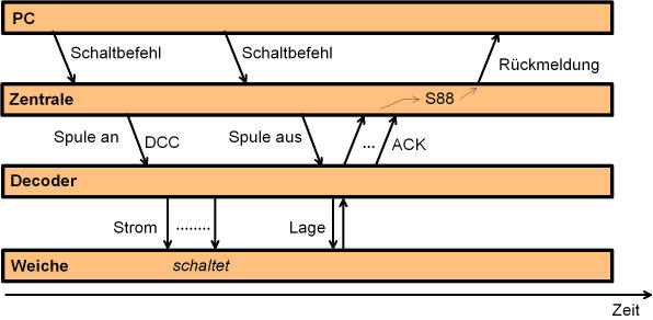
The following sequence is necessary:
- The software in the pc turns on a schedule, inside this schedule a certain turnout is to be used. For safety reasons all signals in blocks running towards this turnout are closed.
- Now the pc sends an accessory command to the command station.
- The command station switches the feedback bit for this turnout to false and forwards the command (activate coil) to the decoder. The decoder will recognize and execute the command.
- After the given switch time the pc will send a 'deactivate coil' command for this turnout.
- The decoder deactivates the coil and
examines the position of the turnout.
The decoder will send back a short
pulse acknowledgment (ACK)
to tell the position of the turnout.
(The examination of the decoder could be either a switch on the rod or the evaluation of the integrated end travel switches) - The command station reads this feedback during the emission of the next preamble. The feedback bit (s88) assigned to this turnout will be set correctly.
- The PC software now evaluates all feedback bits in this schedule and releases the signals and run the train.
External Wiring
-
The wiring is quite simple, in addition to the normal connection by DCC,
all feedback outputs of the OpenDecoder2 are combined and
connected to the CTRL input of OpenDCC.
The decoder, which is currently sending the receipt, pull the ring line to GND, thus current is
flowing through the optocoupler inside OpenDCC. Wiring this feedback line as twisted pair
is recommended.
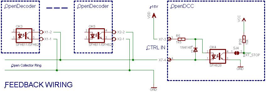
- Notes
Close solder jumper SJ4 on the PCB for OpenDCC, otherwise the processor will not receive the feedback.
Turnout feedback is not possible together with external stop.
Software integration with the existing modules
-
The tasks of the DCC Command Station in the above chain are maaped as follows the the modules:
When a accessory command is received, the feedback bit will be cleared already in the parser. The accessory command is then handled as usual in the underlying layers. There are two possible locations for this feedback bit: inside the s88 module (as a substitute for a external feedback), and / or in memory for the switch positions.
If the accessory command is a 'deativate coil' command, the organizer will attach the property is_feedback to it. Then this command is handled like all others with normal queue processing.
At the layer dccout this property is_feedback is extracted and a at the end of the next preamble, the feedback line is evaluated. This event is then forwarded as feedback message to the modules s88 and organizer.
On the next scan, the s88 module will encounter this message and will include it in the feedback bits, from where the control program inside the PC can recognize and evaluate it. The coding of these feedback bits is defined in S017.
To make the mapping between turnout address and feedback bit easier, it is recommended to use exactly the same numbers for the turnout and for the associated S88 bit. Therefore, turnout feedback should not be used togehter with normal S88 operation, as the messages will overlap. See the Special Options 7 and 16. (For simultaneous operation of turnout feedback and S88: the S88 addressing always starts at 0, the turnout feedback bits must have a corresponding offset. (SO16))
Evaluating the Feedback inside Train Controller
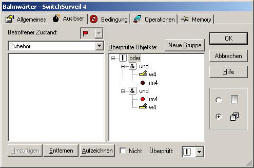
This image shows the evaluation in Train Controller: a flagman is created for each switch. In the trigger condition of this flagman both the position of the turnout (here w4) and the feedback bit (here rm4) are entered (for both directions of the turnout). The flagman gets activated when turnout and feedback does not match.
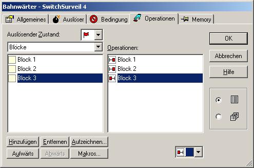
Exit barriers for the neighboring blocks are entered in the action tab. These barriers are towards the turnout.
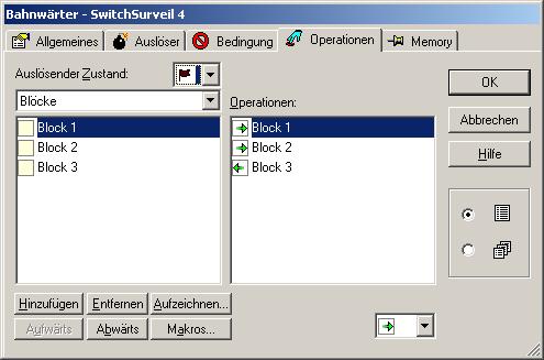
If the flagman gets deactivated, the barriers must be released again. If more than one turnout is affected, you may use a collecting flagman and imly barriers to block in the surrounding.